Introduction
Till now I made 5 little flame-eaters and, to be honest, I seriously had made up my mind to never make any flame-eater again. Nice little things, but as a rule very nervous for divers and elementary reasons. If you don't clean the cylinder and piston after each demonstration, there is a big chance that the engine will run bad or not at all. I always stand and look with bated breath, afraid that the engine will frightened from me or from something else, giving up running as a result. They are like dogs that only listen to their bosses, at least when they have drilled them well. Of course I am exaggerating here, but I am sure many model builders will understand what I mean.
But strange enough this gnaws at me from time to time because in principle flame eaters could be well behaving if they should not pollute that fast due to the hot and corrosive flame gasses and if the frictions in the whole system should be kept constantly and extremely low. So more or less regularly a kind of instigation is coming up with me to once design and make an uncomplicated flame eater, may be against all odds.
Recently I got that feeling again when I bought some small Neodymium magnets for another reason. It occurred to me that it must be possible to make a driving system with very and permanent low frictions for the valve that opens and closes the flame hole in the flame-eater cylinder. In addition the pollution could be made almost neglect able if I could use a glass cylinder in what a graphite piston is moving.
After some brainstorming and a lot of boldness I now think that these two elements can be combinated hand in hand as I will explain later on.
But making a flame hole in a glass tube that can be closed almost air-tight by some sort of moving valve looked a invincible problem to me. But I suddenly realized that a cut-off glass test tube have already two holes from nature. So why make a hole if there are already two of them present? Through one of the holes you can put the piston and you must close and open the other hole cyclically, which still remained a problem. But the solution for that was thrown to me as a present when I put a steel ball on the flange of a test tube with very accurate dimensions. I determined that the air-tightness was surprisingly well, at least comparable or better than with the classic valve that is constantly sliding over a hole in a steel cylinder while the hot and wet flame is messing up the surroundings.
I must say that I have the disposition over some heat resistant Scott Fiolax glass tubes with very accurate dimensions (diam tolerance +/- 0,01mm or better!), also with respect to the ovalty of the flange. Without this excellent quality it would be without any chance of course.
The combination of a steel ball on a glass tube is ideal for a magnet system because you can pull the ball easily and contactless from its seat while the glass tube is unaware of any innocent.
See here the basis for this new design that maybe can result in a cute and neat little doggie.
The design
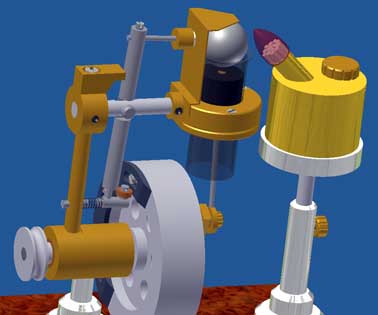
The video and picture below with still only CAD pictures illustrate the typical characteristics of this design.
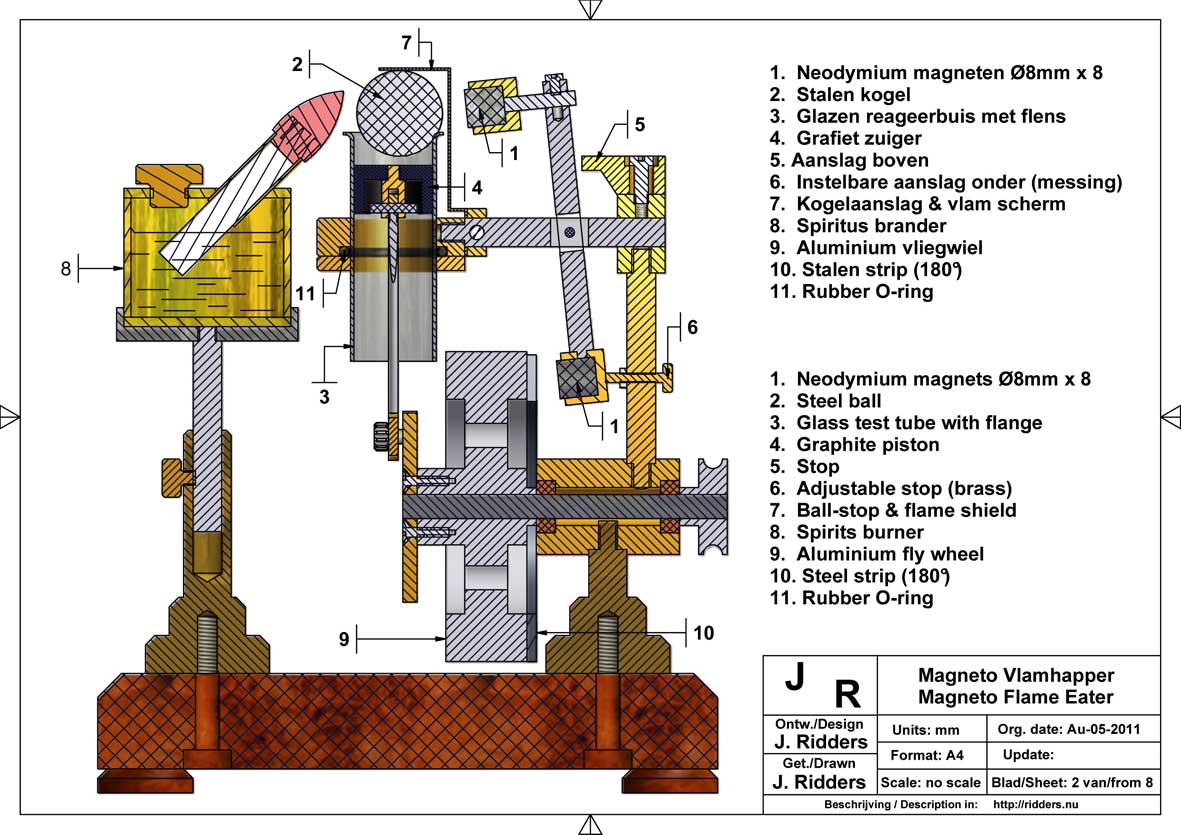
1. The cylinder/piston combination.
The cylinder is cut from the upper side of a heat resistant glass test tube with flange (original diam. 18mm; length 180mm). This tube must have very accurate dimensions with almost zero ovalty because the piston must fit well in it and for all because the steel ball must join the flange with almost 100% air-tightness. I use a test tube from borate silcate glass also known as Pyrex glass. A well known brand name is Schott Fiolax or Duran and if you type this on Google Search you find many world wide suppliers for this kind of tubes with excellent quality; diam tolerance +/- 0,01mm or better!
I cut glass tube as follows:
I clamp the tube in the collet chuck of my lathe machine carefully and let it turn around with low speed. Then I grind the glass on the right spot very carefully and with low pressure with my 30.000 rpm hand grinding tool (brand “Dremel”) with a 0.5mm thin grinding disk, wetting the glass with turpentine on a paint brush. After some minutes the glass will break of. You can grind the sharp edges of the glass piece with waterproof grinding paper on a glass plate.The piston is made from graphite because it can slide with extremely low frictions in a glass tube and it is non corrosive. For that reason it is ideal material for flame-eater pistons.
2. The magnet system
The steel ball that must close and open the upper side of the tube cyclically must have such a diameter that it rest "playful" on the flange without any chance of clamping. My ball has a diameter of 18,3mm while the inner diameter of the glass tube is 16,6mm. The ball is sealing the flange by its own weight.
The swiveling arm contains two Neodymium magnets (Ø 8mm x 8), one on the upper side and one on the bottom side of the arm. There are two adjustable stops for limiting the stroke of the arm. On the flank of the fly wheel there is a thin steel strip over half the circumference which is pulling on the lower magnet when it is passing. In that position the upper magnet is so far away from the ball that it will stay on the flange during the the cooling down and power stroke. If the piston arrives in its upper position starting the suck-in phase the metal strip on the fly wheel just leave the magnet so the upper magnet is pulled in the direction of the ball. If the upper magnet is close enough the ball will be pulled from the glass flange and it will stay there during the suck-in phase. In fact the ball is pulled only 1 to 2mm sidewards, while it keeps resting on one side of the flange making a kind of "half moon" hole through what the flame gasses are sucked-in as the piston is moving downwards. The ball then is resting also against the brass roof that also prevents the magnet for overheating. So the ball makes a small "toppling" movement with the intention to avoid a bouncing effect.As you can see on the animation on the video the ball also acts as an automatic over-pressure valve to eliminate the counter acting effect of such an over-pressure, being a well known negative phenomenon with flame eaters.
The project follow-up
Till today (July-26-2011) I only worked on the design and making the CAD drawings. So there is only paper stuff and that is patient as you will know.
I fully realize that this design has some implicit risks. The Pyrex glass is very well temperature shock resistant but if everything will go well with the steel ball on it is not that sure. The steel ball also will oxidize somewhat due to the wet and hot flame and if that will influence the seal on the flange remains to be seen.
Another possible threat could be a less good cooling down of the flame gasses against the glass wall compared to that with a steel cylinder. In my opinion that will not take immediately any revenge at starting up the engine, but may be it will after some minutes running. But I can live with that if this effect is not too dramatic. On the other hand the tenuous flame gasses are very hot but with low heat capacity so the temperature difference between the in streaming gasses and the glass wall can remain rather significant (I hope).If these three threats might turn out better than I fear I don't see any reason why this thing will not run. The engine will probably have a rather low speed due to the mass inertia of the steel ball and a possible lower temperature gradient, but I wouldn't that at all as long as it runs steady and reliable.
The reality will tell me if I was too optimistic or that the luck was on the side of the fool: "the proof of the pudding always in the eating".
So I now start building this strongly deviating flame-eater and I will write down my trials and errors in a kind of logbook as I did before.
If I succeed in letting this thing run I will show it with some satisfaction; if not I will polish it and put it in my "fantasy gallery"
Logboek
July-26-2011
I need some two days to finish the drawing plans in detail before I can start the real building. This plan will only be available after I am sure that my engine is running properly. According to my estimation I will know that after some 3 or 5 weeks from now.July-28-2011
Today I made the graphite piston and tested the air-tightness of the ball on the glass flange: the piston kept hanging in the glass tube with the ball on the flange, so it seems that the first hurdle seems to be taken! If that should not have been the case I could have forget the whole project I think.
The second important test was heating the ball when laying on the glass flange. Except the fact that both parts grew very hot nothing happens: no glass burst and no ball colouring for the time being. So this second critical hurdle seems to be taken also!
Now I can start building the rest of the flame eater with some confidence.
August 4th 2011
The flame eater is almost ready. I implemented two improvements/changes:1. I "halved" the screen over the steel ball that acts as a ball stop and as shield for the flame to avoid overheating the upper magnet and mounted it on the other side of the ring that fixes the glass cylinder. The idea is that this screen will be heated much less and the flame will not be hindered by it.
2. I discovered that I can omit the blade spring on top of the swivel arm because there is always enough pulling force from the steel ball so the magnet will also move to the ball at the moment the lower magnet is away from the 180 degree steel strip on the fly wheel. Without this blade spring the system becomes somewhat more simple because there will be one item less to adjust. On the place where this blade spring was fixed I now mounted a stop for the swivel arm so the lower magnet will always be some 1mm free from the steel strip on the fly wheel.
August 6 2011
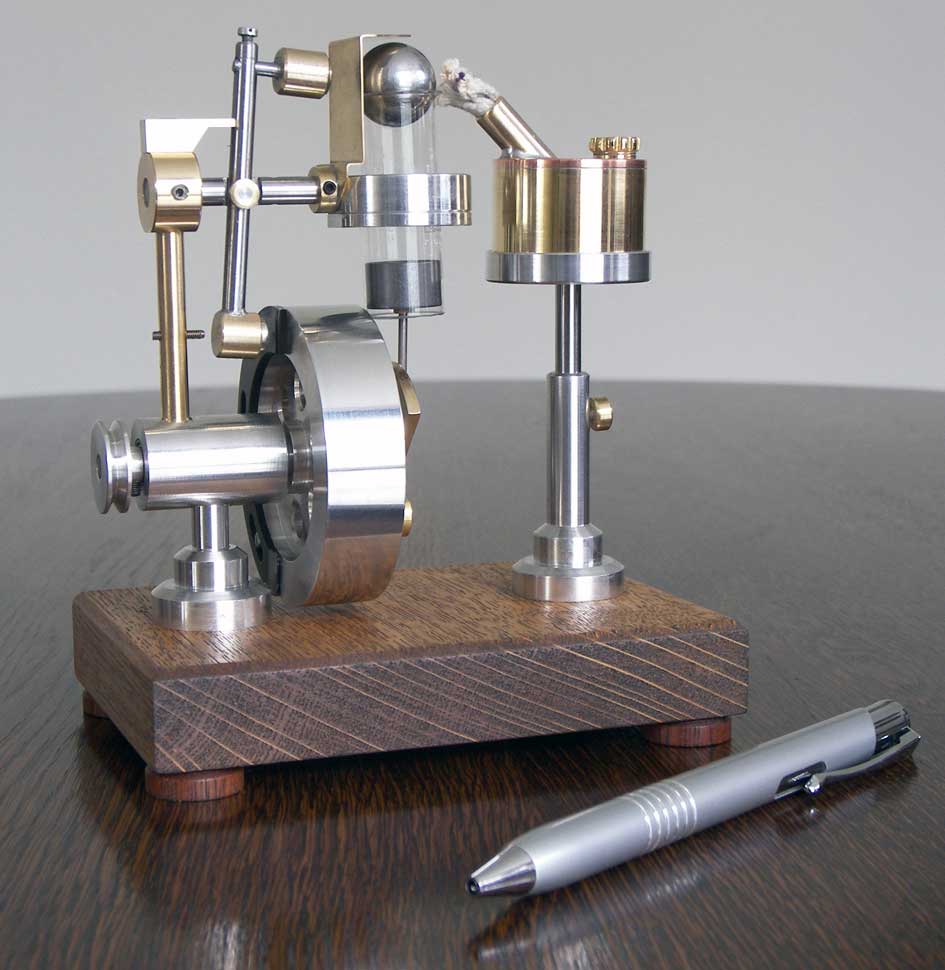
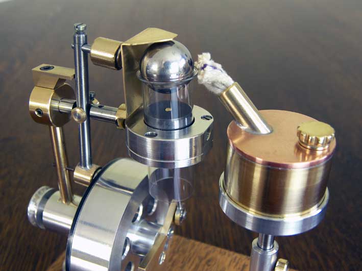
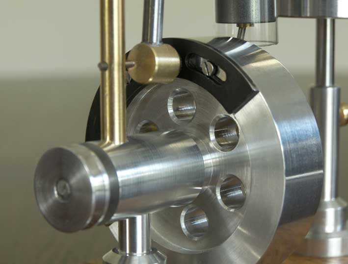
The thing is ready now so I could make some real life pictures; see below and on the upper right of this page.
Of course I tried to start the engine after making this pictures, but he refused to do that for the time being. When I turn the fly wheel around slowly by hand everything works exactly as I expected; very funny to see that. With the flame the engine tend to run, but not continuously and it acts strange. I believe something happens that I didn't think of before: the swivelling arm is moving very fast due to the very strong Neodymium magnets resulting in very strong bumps against the (mainly) upper stop. As a result rater heavy trembling occurs and I assume that the ball is shaking somewhat over the flange of the glass cylinder not closing continuously and/or in time. It is a fast process so I can't see that, but it is more than likely that this happens.
So I will have to do some experimenting and debugging, but I am accustomed to that: I never made an engine that runs immediately after I finished it. May be I have to do some further timing adjustments also.
I now have a weekend to think about solving this "shaking" event.
August 11 2011
I don't like to admit and never give up soon, but I now think this bold thing will never run, although not according to this concept. Pity of course but in fact not such a big surprise because there were several risks on beforehand. It could have been possible but this time luck wasn't on my side.
An important problem was unexpected: at the moment the magnet leaves the metal strip on the fly wheel it is pulling at it with such a force that the power of the engine could not overcome that. At that moment the piston is at its lowest position to start at the power stroke because the trapped flame gasses are cooling down (see the animation on the video). The force on the piston is relative low (as with all flame eaters) and not able to pull the magnet from the metal strip unless the fact that it has no physical contact with that. I did some experiments with smaller and less strong magnets but that doesn't solve the problem either. Furthermore the adjustment with weaker magnets becomes more critical because the upper magnet must be pulled from the steel ball in all cases and that must be done with sufficient force from the lower magnet.
I thought that this magnet system would be almost without any friction but the magnetic forces that came in place at the moment the magnet passes the end of the metal strip are even more deadly!
Out of sheer desperation I replaced the lower magnet by a small ball bearing that is running against the metal strip on the fly wheel as is common with classic cam systems; see picture below:
The thing made some strokes indeed, but after some time it was as dead as mutton again. So the force to pull the bearing over the metal strip was significant less, but the power of the engine appeared to be still insufficient. The steel ball showed temper colors after some time and a there was a brouwnish deposit araound the gap where the flame was sucked in, on the ball and also on the glass flange. I have the feeling that with that the ball didn't seal well enough anymore. When I checked that by pressing the ball somewhat on the flange I burned my fingers and a tiny burst in the flange occured. Maybe caused by my panicle reaction because before that the glass withstand the heating by the flame without any problem. I think this was my punishment for all my nagging.
I immediately immersed my fingers in a bucket with water and apart from a little blister I have nothing left over, besides the little frustration that drained away fast by the way. After all I did estimate my chance of success not much more that 50% and this time I was at the wrong half side.
It is as well be possible that the low engine power is caused by the fact that the cooling down of the hot flame gasses against the glass is much less efficient as against a steel cylinder with cooling fins. I now can't separate this possible negative effect from a eventual leakage along the steel ball surface. Maybe both effects occur and are being enforced in negative sense.All together it leads to putting this "stunt" engine in my "fantasy gallery" and to be honest I think it will not escape from that anymore. Till now there was only one of my models there (4- stroke engine with rotary pistons) so that got company now. Till today I made about 40 little engines and when only two of them died before being born I may not complain I think. I had some nice hours with designing and making, but I apparantly was begging the Gods and Gods can be sincere but also very stringent.
To wipe away my little frustration I started cleaning up my work shop thoroughly, painting everything new that can be painted. Not a luxury after ten years according to my wife who annoyed herself all the time about the enormous garbage there. Could be that a workshop that looks like our living room as my wife keeps it all the time will bring me more luck next time.
October-9-2011
New developments and new luck?
A week ago I took the "Magneto Flame Eater" of the gallery shelff again because dumping this project was gnawing at me and because I got some new ideas that probably could solve the problems.
The reason for the failure was the inability of the engine to overcome the magnet force in the rotation direction at the moment the lower magnet must leave the metal strip on the fly wheel. So one of the obvious things to do is to increase the engine's power.
Without having any real evidence I assumed that the low engine power was a result of the bad cooling down of the flame gasses against the glass wall of the cylinder. Glass is a very bad heat conductor so I took the courage to make a new cylinder from aluminum, being a very good heat conductor. I made a conical seat on top of that cylinder on what the steel ball is resting by its own weight, comparable with the ball on the flange of the glass cylinder.
And see: the engine suddenly showed serious signs of life, confirming for me that the flame gasses are cooling down much better in the aluminum cylinder with a higher engine power as a result. The engine was running more or less but it still regularly keeps stopping at the moment the magnet was trying to leave the metal strip on the fly wheel. I tried to optimize the game of forces of both magnets and sometimes it resulted in fairly running, but the adjustment was unacceptable critical.
I even made seven magnets in the fly wheel instead of the metal strip that push the lower magnet on the swiveling arm away other than attracting it. But the same problem occurred when the first magnet in the fly wheel was trying to pass the magnet on the swiveling arm: the pushing force in the wrong fly wheel direction was too big for the engine's power.
I even did a more "foolish" experiment by removing the whole magnet system and pushing the ball from its seat with a little notch on the piston when it arrives at its upper position. The flame gasses should be sucked-in then through the opening between the ball and its seat. But this only can work of course when the ball is falling on its seat at the moment the piston is in its lowest position; not much earlier or later. It is a fact that the ball is falling back on its seat with some retardation due to the mass inertia and I could not believe my eyes when the engine was running more or less sometimes. But without any additional arrangement the timing of this process will not be under control: the ball mostly will be too late or too early on its seat and only in the accidental case the ball closes the cylinder at the moment the piston is in its lowest position the engine will run, but not for long.
These experiments learned me some important facts that maybe can help me to make this project to a success after all:
1. The combination of a graphite piston in a aluminum cylinder appears to be a very good one in contradiction to my expectations. A very thin graphite film occurs on the cylinder wall causing a very low friction. Even more important is that this combination apparently don't suffer from fast pollution from the hot and wet flame gasses, causing growing frictions being a disadvantage of almost all flame eaters.
2. The steel ball is sealing well on its aluminum seat and keeps doing that despite long lasting heating by the spirits flame. It looks as if this will not be any problem.
I now think I can eliminate the biggest part of the counter acting magnet forces by only maintaining the little upper magnet that "catches" the ball when it is pushed up by a notch on the piston. The ball must be kept in that position by the magnet during the time the piston is moving downwards, sucking-in the flame gasses. A more simple arrangement must move the magnet away from the ball at the moment the piston arrives in its lowest position so the ball will fall then on its seat again. In fact the magnet only needs to be pushed away for a short time because the ball is out of the magnet field until the piston pushes the ball upwards again in its upper position. So a simple pin on the fly wheel could be sufficient to push away the magnet on a lever arm for a short time. The timing is a matter of a right fly wheel positioning in relation to the crank shaft that drives the piston.
I now am making a system like this and within a couple of days I will show here some drawings and other picture material to make clear what I mean; of course only when things are working out according to my present expectations.
October-20-2011
No luck and end of the project for the time being.
I was too optimistic again. If I turn the flywheel manually the process is exactly as I want: the ball is lifted by the notch on the piston when he arrives in its upper position and the magnet holds the ball during the time the piston is moving downwards, sucking in the flame gasses. When the piston arrives in its lowest position the magnet is pushed away by the mechanism and the ball falls on its seat again.
All perfect as far as I can see, but apart from a rare sign of life I cannot let this thing run. I investigate all thinkable causes with numerous experiments but the engine is not willing to tell me his secret. I will not bore the reader with a complete report to avoid only make confusion while the final result is zero.
I am getting the fearing feeling that the problem is more or less fundamental: the ball is sealing well on its seat when it is in rest there, but if the ball is only bouncing for a split second at the moment he falls on its seat the vacuum in the cylinder will disappear immediately which is fatal for a flame eater.
I can't see this eventual bouncing phenomenon because the process is far too fast for that, but I can't think of any other reason for the failure anymore.
If I don't get an idea to eliminate this bouncing I fear that this design will be put on ice for ever. As long as I don't get some good caprice I must rest with the idea of a closed project without result; sometimes an inevitable part of the hobby I think.