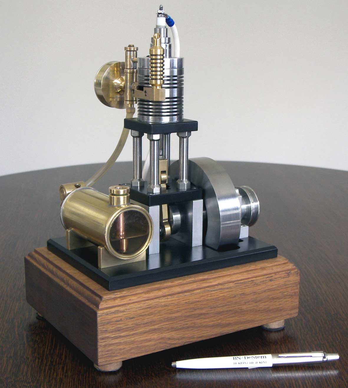
A pressure controlled 2-stroke engine
The idea behind this unique two-stroke design
From a mechanical point of view a 2-stroke internal combustion engine is much more easy to make then a 4-stroke engine: there are no moving intake and exhaust valves with their rather complex driving systems with cam shafts, tumblers and a 2 to 1 distribution system. The flushing process for the gas mix takes place on both sides of the piston. As the piston is moving upwards to its TDC position the fresh gas mix is compressed and at the same time the new fresh gas mix is sucked in the cylinder room below the piston. When the piston is forced downwards due to the ignition of the compressed mix above the piston ( power stroke) the new fresh gas mix is compressed below the piston. At the moment the piston reaches the exhaust opening in the cylinder two things happen at the same time: the burned gasses escape through the exhaust opening in the cylinder and the new compressed gas mix is flushing above the piston through a channel and an intake port in the cylinder wall that is opposite to the exhaust opening. This new gas mix must fill the room above the piston and must also drive the remaining burned gasses out of the cylinder with a minimum loss of fresh mix. When the piston starts moving upwards again due to the absorbed rotation energy in the fly wheel both intake and exhaust ports are closed again by the piston and the cycle repeats. So there are only two strokes of the piston at each revolution of the fly wheel.
I made a very simplified model of such a two-stroke engine and the animation below shows the above described process.
Animation of the classic two-stroke process
The construction of a 2-stroke engine might be more simple then that for a 4-stroke, but filling the cylinder with 100% fresh gas mix every new cycle is much more difficult and in fact always worse than with a 4-stroke. When some burned gasses remain in the cylinder the engine runs bad or not at all; the engine is "poisoning" itself. If to much new gas mix is leaving the cylinder before the ports are closed there is an efficiency loss and the unburned gas will burn in the exhaust muffler, mostly incomplete causing bad smells and pollution.
Another disadvantage of a two-stroke engine is that you cannot grease the piston with oil in the crank box as this is done with a four-stroke engine. Therefore greasing is accomplished by mixing some oil with the petrol in the tank. This oil is burned also during the combustion, causing pollution and bad smells.
So, the main and only advantage of two-stroke engines is that they are relatively small with low weight. That's the reason why they found widely applications in small machines like motor bikes, grass mowing and sewing machines, etc.
How difficult it is to realize a good flushing process I encountered while building my "Simple Two-stroke Engine". It took me numerous experiments and much time to succeed in letting this engine run well. I had to make several new cylinders before I finally found a good one with six intake ports and with the right port dimensions that determine the timing and gas flow through the cylinder room above the piston. It was a big triumph for me to see this engine run so well at last but I could not push the thought aside that there must be a way to improve this flushing process significantly, at least for a model engine.
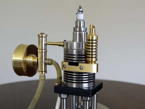
Injecting the gas mix at the top of the cylinder in stead of half way near the exhaust opening looked more logical to me. But this injection must occur exactly at at the moment that the piston opens the exhaust port in the cylinder. That's way the intake port is at the same height as the exhaust port in classical two-stroke engines so this opening and closing can be done with the piston. So, for the timing of an injection at the top a separate mechanism must be introduced. Of course this could be done with a mechanical driven valve and may be someone did this before. But this would do much violence to the simplicity of the two-stroke being its greatest advantage.
My positive experences with the simple check ball valve between the cylinder and the "Petrol Vapour Carburettor" brought me the idea to add a second one to realize this timing of the intake at the top in a very peculiar way. I will clarify this with the help of the animation below.
A ball valve only opens when the pressure below the ball is higher then above the ball. For the upper valve this is only the case, and for a very short time, when the piston reaches the exhaust port. The pressed gas mix below the piston and between the two ball valves is injected then, filling the cylinder and pushing out the remaining burned gasses. Before and shortly after that moment the pressure above the ball in the upper valve is always higher then below the ball. When the piston is moving upwards there is an overpressure above the ball (gas mix compression) and a lower atmospheric pressure of the sucked-in fresh gas mix below the ball. When the piston is moving downwards there is a high overpressure above the ball due to the combustion (power stroke) and a much lower overpressure of the compressed fresh gas mix below the ball. So also during that power stroke the upper ball valve keeps closed until the piston opens the exhaust port.
So the timing of the process is exactly right and automatically controlled by the alternating pressures in the system. That way I called this engine the "Pressure controlled Two-stroke".
The advantages of this design.
1. Although I can not prove it for 100% I am convinced that this flushing process is better then the classic one, at least it is much easier to realize. Fact is that my engine did run immediately after I have finished it without any of the problems that I had to overcome with my first two-stroke as I mentioned above.
2. The cylinder of this engine is much easier to make then the one of it's classic opponent. It is all straight with only a simple exhaust hole in it.
3. The timing of the process is 100% physically determined and always correct. With the classic design the timing is determined by the mechanical dimensions of the intake and exhaust ports in the cylinder, absolutely and in relation to each other. If you make one mistake or error there you mostly are condemned to make a complete new cylinder.
4. You don't need special geometries of the intake port, the shape of piston head or cylinder head to force the in streaming gas mix at the top of the cylinder.
5. Together with the excellent performance of the universal "Petrol Vapour Carburettor" this little engine is very reliable, easy to start and running very smoothly and friendly.
6. In fact this engine doesn't contain any difficult part any more. The model is well doable with relative simple and basic lathing- and milling work with standard materials. No castings, forced cooling and greasing mechanisms, assuming that you are satisfied with no heavy duty usage but successful demonstrations for about 5 tot 20 minutes. To be honest I cannot hardly imagine that it is possible to make a more uncomplicated IC engine than this one.
The work-out
I started with a working sketch like the final cross section above putting the rough and main dimensions in it. Subsequently I made detail sketches of the most important parts and start building by means of those sketches. Doing so I added the remaining parts successively.
Building the engine took me about 120 net man hours, designing and drawing the details inclusive. It was almost a "digital" event: the engine runs immediately because the principle is valid, or it will never run because the design carries a fatal composite error. The first was the case: I only had to implement small modifications to let the engine run.1. The cylinder/piston combination.
Because I wanted to make a somewhat smaller engine I choose for a cylinder bore of 18mm in stead of 24mm with the first two-stroke.
For the cylinder as well as for the piston I used pearlitic cast iron again. In this case this material is at least highly preferable, may be even conditional to make it possible to omit any systems for forced cooling and greasing. The thermal expansion of cast iron is very low and in any case equal for cylinder and piston. Together with the fact that it is more or less self-greasing due to the relative high carbon grade, it prevents jamming of the piston, even without forced cooling and oil greasing!
Furthermore cast iron is highly temperature resistant and working-up is rather easy. Anyhow it is recommendable to put a single oil drop on the piston from time to time, for instance through the exhaust port. Not necessary to avoid jamming, but to keep the surface of piston and cylinder in good condition, mainly before a longer storage of the engine.
The vertical position is a logical consequence of the positioning of the ball valves which stand right up because they don't use compression springs here (see item 2 below).
For a good engine performance the piston must move very smoothly in the cylinder but on the other hand it must fit almost air-tight in the cylinder. Therefore the bore in the cylinder must be smooth and exactly cylindrical. The diameter differences over the bore length mustn't exceed 0.01mm. I realized this rather easily by reaming the cylinder bore manually with an adjustable reamer and ample oil , turning around the cylinder several times with the same reamer adjustment until the reamer can pass easily through the bore. Then I adjust the reamer a fraction wider and repeat this treatment again and again until hardly any diameter difference could be measured any more with a micro meter. This makes the taper equal or less than 0.01mm. This way of working can compete with real honing and is a good alternative if you don't have honing equipment.
I first screwed the piston axis in the somewhat over measured piston and pin-fixed it. With this axis in the collet chuck of the lathing machine and with the piston against the rotating centrer, the piston was trued up so that it fixes somewhat clasping in the cylinder. Then the piston was manually polished in the cylinder with some fine grinding paste. The result was an under size of the piston diameter of 0,01 to 0,02 mm. The clearance between the cylinder bore on the one hand and the piston on the other hand must not exceed 0.03mm.
The engine runs perfect with that and without piston rings ! It is recognizable better than with piston rings because the friction of them slow down the speed of this small engine with rather low power.
I made a Teflon glide bearing for the piston shaft. It can be pressed in the central hole of the cylinder bottom plate and if you drill the hole with fitting H6 or H7 the piosto shaft is gliding in it with low friction and good sealing. I have very good experiences with such wear resistant Teflon bearings.
This glide bearing can also be made from bronze as long as the piston shaft is running in it with low friction and almost leak free.
With empirical experiments I discovered that it is important to adjust the piston in the vertical way so that the distance between the piston and the bottom cylinder plate is it as small as possible in its lowest position. This adjustment can be done by screwing the piston rod in the fork till the piston just touches the bottom plate and than screw it counter wise a little again and fixing this adjustment with the locking nut. The result is that the piston is about 1mm below the exhaust opening in the cylinder in its lowest position. Doing some trouble shooting with a copy of this engine made by somebody else I found out that this adjustment is absolutely crucial to let this engine run well !! It has to do with the flushing process above the piston which is very sensitive with two-stroke engines. When the piston in this case is adjusted too high the engine is "poisoning" itself because the burned gasses are not driven out completely and/or are pushed somewhat back when the piston is moving upwards again.2. The system with the two ball valves.
The parts of this system are all made out of brass and can be made with simple lathing operations. The 45° ball seats must be made straight and smooth with a small and sharp lathe tool.
You can use standard steel balls with diam 3/6 inch (4.8mm).
Originally I put a small spring in the ball valve to prevent ball bouncing. However, adjusting the spring pressure appeared to be very critical. I discovered that the valve operates even better without springs on condition that the free space for the ball is limited to 0,5mm. More space causes bouncing and floating causing irregular engine behaviour. If one apprehends themselves to the measures on the drawing plan this requirement will be met.
It is recommendable to seal all the screw assemblies, for which I simply used sanitary kit, which has the advantage that the screwed assemblies can be dismantled in case this should be necessary. Take care not to spoil kit on the brass ball seats !
Just as with my first two-stroke engine a small expansion vessel appears to be inevitable. In fact this volume is a substitute for the volume of the crank case in every "normal" two stroke engine. This volume plays an important role in the pressure and flushing process of every two stroke engine. See for a more precise explanation the concerning part in the text on the page for the "Simple Two-stroke Engine".
I determined experimentally that the optimal volume for this vessel is about 12cc in this case, but that is not very critical.
3. The Petrol Vapour Carburattor.
You can find detailed information about this Petrol Vapour Carburattor on the concerning page of this website. Because it is universal design it has a separate drawing plan.4. The exhaust muffler.
The engine runs well without muffler, but with one still more quietly than he is already and it looks better too.
As two-stroke insiders know, a muffler can have a positive influence on the behaviour of the engine. It has to do with counter-pressure for the out streaming gasses and/or damping pressure waves. I miss the exact understanding for this, a thermodynamic phenomenon that is not easy to describe I assume.
The horizontal groove with the height of 3mm in the mounting block for the muffler causes the mentioned positive effect. In fact the vertical muffler itself has only a cosmetic function. If this groove is higher the engine acts as if there is no damper at all; with a smaller groove the engine runs less good or finally not at all.5. The ignition of the spark.
It is my experience that two-stroke engines need a spark with relative high power (5 to 10W). Initially I tried a piezo element for the ignition just as I did successfully with my four-stroke engines, but the my two-stroke engines run with missing strokes or not at all.
I use a rather small 6 or 12 volt ignition coil for a classic motorbike which can be build in the wooden base of the engine as well as the electrical switch with capacitor. The figure below shows the classic electrical circuit for such an ignition coil. Don't use the small high tension coils as nowadays are used in modern motor bicycles; they mostly have specific electronic power supply from a generator on the fly wheel axis!
For the external power source I use the rechargeable accumulator for my hand drilling machine. It can easily deliver the required 3 to 5 amps for the primary coil current and the engine runs half an hour on it or longer.
A cam disk that is mounted on the flywheel axis operates this switch. The spark must occur exactly at the highest position of the piston or a very small fraction earlier. This can be adjusted by turning the flywheel with cam disk over the crankshaft.
The assembly of these ignition components is not part of the drawing plan because this depends on the availability. Besides this is more a matter of improvisation on spot and will cause hardly any problem I assume.
Starting-up the engine
The fuel for this engine is standard auto car petrol. The petrol tank must be filled half, which is enough for about 20 minutes runtime or more. Mostly one shall run this engine not much longer than about 5 minutes or so, which is more than enough for a successful demonstration.
Yoy can start-up the engine with a loose rubber belt around the pulley on the fly wheel axis and around some similar pulley in the head of your hand drilling machine. While doing that turn the adjuster on the carburettor for adding extra air to the gas mix first totally open and then close it somwhat gradually untill you here the enengine takes over. You can regulate the speed of the engine anywhere between 500 and 2000 rpm with this adjuster valve; see for more details the concerning page about this carburetor.
The cylinder temperature will stabilize around some 110°C after 5 to 10 minutes, which will not cause any trouble at all.
Video:
Drawing plan
I made a CAD drawing plan for this engine that is available for any-one interested; click here for a request.


Very nice replica made by Huib Visser:
Nice replica made by
Branislav Streicher:
Nice replica
made by Bart
Nice replica made by
Leonidas Farmakis:
Nice replica made by
David Schacherleitner: