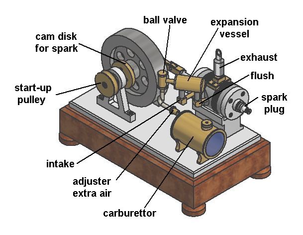
A Simple 2-stroke engine "Debbie"
Introduction.
For model builders with limited experience and mediocre tools, making a 4-stroke combustion engine will not be that easy and especially beginners may think that it is not feasible for them. Things like a difficult crankshaft, valves with their complex drive mechanisms, a distribution system, castings, a crankcase, a carburettor, forced cooling and lubrication systems, piston rings, precision grinding, etc. seems to be the exclusive privilege of a few and quite experienced specialists in this area. I myself am a modeller without a mechanical background and I also only have limited tools. That is why I always strive for the simplest possible designs, so that the motors can be made with only standard turning and milling work and with standard materials. A reliable and nice running engine is always my only goal other than high performance and/or efficiency. After creating two fairly straightforward 4-stroke models ("Atkinson" and "Otto") I set out to design a much simpler combustion engine. I knew in advance that this would have to be a 2-stroke engine because a 2-stroke has no moving intake and exhaust valves and no distribution system so that already quite complex work would be eliminated. I venture to say that the result is a "tight" and rather good looking little engine that runs very reliably and quietly with a simplicity that can hardly be surpassed in my humble opinion. It seems to me an excellent model for beginners.
The principle of a conventional 2-stroke engine
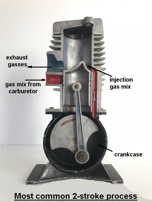
As with any combustion engine, there are 4 process steps here: inlet of the fresh gas mixture from the carburettor, compression of this gas mixture, combustion and exhaust of the burned gases. With a 2-stroke, however, these process steps are divided over both sides of the piston at the same time , so that the cycle can be completed in two strokes, while the 4-stroke needs 4 strokes for this. As the piston moves upwards, the fresh gas mixture at the bottom of the piston is sucked in while the gas mixture from the previous cycle is compressed above the piston. When the piston moves downwards again due to the expansion of the ignited gas mixture above the piston (the power stroke), the fresh gas mixture below the piston is compressed in the crankcase. The moment the piston reaches the exhaust hole in the cylinder wall the burnt gases escape out and a fraction afterwards the compressed fresh mixture in the crankcase is injected above the piston through the inlet port opposite the exhaust port. The fresh gas mixture flushes the last burned gases out of the cylinder and is then immediately compressed above the piston as it moves upwards again due to the flywheel effect. When the piston reaches its top position, this compressed mixture is ignited and the cycle repeats.
It is somewhat difficult to make the purge process such that all burnt gas residues are expelled from the cylinder without escaping fresh gas mixture directly and unused through the exhaust port. That actually never works for 100%, which is why a 2-stroke engine is always less efficient than a 4-stroke with what the process is better controlled with driven inlet and exhaust valves. But the much simpler system of the 2-stroke engine and the relatively small dimensions and weight has made it very popular, especially for small vehicles such as mopeds and scooters and other small machines such as a chainsaw.The design of this of this simple 2-stroke engine.
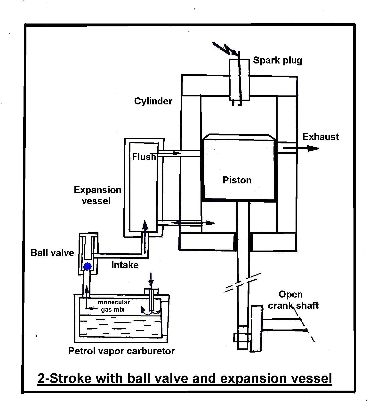
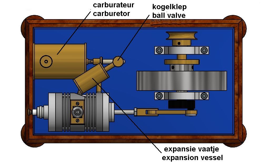
The crankcases for 2-stroke engines are complicated castings with airtight lead-throughs for the crankshaft that are therefore very difficult or impossible to make by amateur modellers. To eliminate such a crankcase I made an external crankshaft with connecting rod as are common on steam engines. This made it possible to close the bottom of the cylinder with a simple plate containing a bronze guide bush for the straight piston rod. This open crankshaft only has a crankpin on one side on which the connecting rod can be easily mounted. Besides that a crankcase is the housing for the crankshaft, it also has the function of not allowing the pressure of the compressed gas mixture under the piston to become so high that an opposing force is created on the piston when it moves downwards during the power stroke. Because this model lacks the crankcase, I have installed an expansion vessel between the cylinder and the carburettor that takes over this function of overpressue limitation. Experimentally I have determined that the volume of this expansion vessel should be approximately 12cc with this design. Between a petrol vapor carburetor and the expansion vessel there is a ball valve that opens and closes automatically at the right moments in the process cycle.
The process cycle.
When the piston moves upwards an underpressure is created under it, causing the ball valve to open automatically. As a result fresh gas mixture is drawn from the carburettor under the piston and into the expansion vessel. At the piston top position the spark comes on the spark plug which ignites the compressed gas mixture from the previous cycle, pushing the piston downwards during this power stroke. During this downward piston movement the ball valve also closes automatically preventing the gas mixture from being pushed back into the carburetor while an overpressure of fresh gas mixture is created in the expansion vessel. When the piston head reaches the exhaust hole in the cylinder wall the burnt gasses first escape to the outside air and a fraction after that the connection to the expansion vessel also opens. At that moment, the compressed fresh gas mixture therein is injected into the space above the piston and thus flushes that space through with this fresh gas mixture. If the piston moves upwards again due to the flywheel effect this process cycle repeats itself.
The cylinder/piston combination.
I made both the cylinder and the piston of pearlitic grey cast iron (GG25). This material is very wear-resistant, is somewhat self-lubricating due to the relatively high carbon content (approximately 8%) and does not have the tendency to fret when the piston moves up and down in the cylinder. The thermal expansion is low and equal for the piston and cylinder so there is no chance of seizing as the temperature rises. Both the diameter and the stroke of the piston are 24mm, which means that the active cylinder capacity is approximately 12cc. The cold compression is 4 to 5 ato. For various reasons (including simplicity) I have chosen not to use piston rings as is the case with all my engines. This is also not necessary if the piston is made to fit nicely in the cylinder with a play of maximum 0.03 mm. This piston fit is one of the most important preconditions for good and reliable running of the engine. Honing is the best way to make a cylinder bore nice and smooth. However, most modellers like me don't have the equipment for that. Therefore I proceed as follows:
Roughly drill out the cylinder hole step by step and then turn it out to the desired diameter with approximately 0.1mm undersize. Then manually clear this bore with an adjustable reamer because it then searches itself into the cylinder bore. Clamp the reamer with the flat end of its cone in the vise; so do not turn the reamer but the cylinder over the reamer in the vice. Always add plenty of oil. When reaming, invert the cylinder several times with the same setting of the reamer until it runs smoothly through it. Then repeat this procedure with the reamer set a fraction larger. Repeat these operations until there is actually no longer a measurable diameter difference over the entire length of the cylinder bore, which will then also be nicely smooth. The resulting diameter does not have to be exactly the same as that in the drawing because the piston is only made to fit in the cylinder after this, as follows:
Turn the piston until it fits somewhat "hooking" in the cylinder. By manually polishing the piston in the cylinder with a fine abrasive paste (eg car cleaner Commander no. 4), a fit with a play of 0.02 millimeters or even less is created! The result is that the friction is so low that the engine turns "as if driven by the wind" while there is more than enough compression, even without piston rings. This way of making the cylinder bore is very similar to honing and with a little patience it is hardly or not inferior to that. In any case, it works well with pearlitic GG25 grey cast iron, mainly because this material is somewhat sandy and can therefore be easily machined. The cylinder temperature never exceeds 120 degrees Celsius so that forced cooling is not necessary. Dosing a single droplet of oil on the piston through the exhaust hole in the cylinder wall is recommended when the engine is stored for an extended period of time and is sufficient to keep the surface of the piston and cylinder "in good condition".
The ball valve.
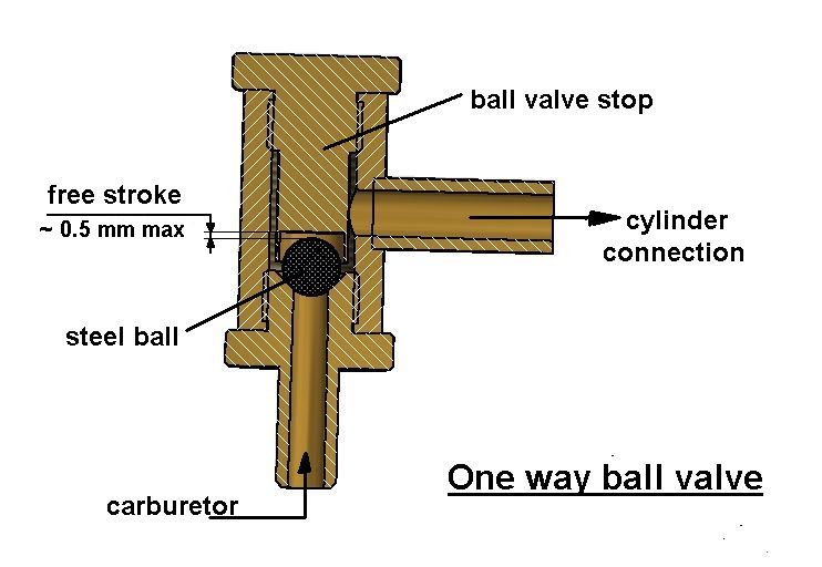
The brass ball valve contains a steel bicycle ball that rests on its conical seat, which must be made nicely smooth with an apex angle of 90 degrees. When the piston in the cylinder moves upwards, an underpressure is created above it, which automatically lifts the ball so that a gas flow is created from the carburettor to the cylinder space under the piston. When the piston moves downwards again, the ball is auomatically pressed back onto its seat due to overpressure, preventing a backflow of the gas mixture to the carburettor.
The frequency of this ball movement is quite large: for example 17 times per second at a motor speed of 1000 revolutions per minute! To prevent the ball from bouncing and therefore the valve will not open and close in time, the free play of that ball must be small. Experimentally I have determined that the free stroke should not be more than 0.5mm.The Gasoline Vapor Carburettor.
As with all my internal combustion engines, I also used the petrol vapor carburetor here instead of a classic carburetor with venturi and fuel nozzle. In fact, it's a simple facility in the fuel tank that allows the sucked-in air from the outside to brush over the gasoline surface and then mix 100% molecular gasoline vapor with air. This carburetor is much easier to make and performs great without the risk of a sooty spark plug and/or engine "drowning". For the description and operation of this carburettor, click here for the relevant page on this website.The spark ignition circuit.
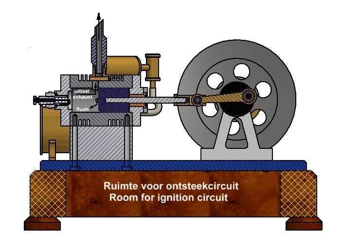
The wooden base of the engine has a recess to accommodate the spark ignition circuit. For this I used a well-known circuit with an ignition coil from a classic car or motorcycle. A bit large, but easy to build in and with a very reliable high-energy spark that is necessary for 2-stroke engines. I usually use the battery of my hand drill for the external power supply of 12 volts. Any other circuit that provides a good spark is of course also good, but most of the small ignition coils used today for mopeds, scooters, saws, etc. are not suitable because they require a different supply voltage that is usually supplied by a generator on the flywheel .The spark plug.
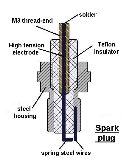
The spark plug is my own design as I successfully use it for all my combustion engines.
The insulator is made of Teflon, which is screwed into the steel housing with fine-metric thread. The high-voltage electrode is soldered into an M3 threaded end that is also screwed into the Teflon with fine-metric thread. A solid connection is thus created which is also airtight. Teflon is an excellent electrical insulator and it completely withstands the temperature of gas ignition. It is of course always possible to use a suitable purchased (small) spark plug and to adjust the thread in the cylinder head if necessary. However, the homemade spark plug usually works better on my model engines than a purchased one, although I've never understood why.
The flywheel.
The flywheel must have a decent mass to run the engine at low revolutions. The dynamic energy of a "bicycle wheel type" flywheel is E=½mw²r² where m is the mass, w is the angular velocity and r is the radius of the flywheel. The flywheel is made of steel with a diameter of 116mm and a width of 25mm. The mass is then about 1.2 kilograms and the dynamic energy about 3 Nm at 500 revolutions per minute.
And last but not least.
-The engine can run on regular auto car gasoline and the speed can be regulated between about 300 and 1500 rpm with the adjustable regulator on the outlet of the carburettor for the inlet of extra mixed air. Instead of regular car petrol, "Coleman Fuel" is preferable to which the engine reacts even more pleasantly and which has little or no smell. This Coleman Fuel is used as fuel for camping stoves and can be purchased at any camping equipment store.
- The engine can be started with a loose belt around the pulley on the crankshaft and a similar pulley in the head of a hand drill. But when everything is set up correctly, the engine can be started easily with a manual push on the flywheel. During start-up, adjust the regulator on the outlet of the carburettor for the addition of additional air so that the engine takes over audibly. The speed is easily adjustable around this setting. The fresh fuel setting will generally be such that there is a lot of extra air and relatively little gas mixture from the carburettor tank. One often tends to the opposite, but that is absolutely wrong because a mixture that is too rich is quickly created and the engine will certainly not start with that. With a half full tank, the engine will run for 15 minutes or longer.
- This engine model is not intended for heavy work, but for running 5 to 10 minutes at the most, which is usually more than sufficient for a successful demonstration.
Drawing plan.
Click here for a request of the CAD drawing package that I made for this engine. When sending it I always add tips in case the engine does not run well, see also the trouble shoot section at the end of the video below.
Note:
The engine in this video is still the first version with a relatively large flywheel. Later it turned out to me that a smaller flywheel (that also remains just above the bottom plate) provides sufficient retention to keep the engine running during the idle stroke.
Video:
This engine made by students
WICO campus Belgie
(see ca 1,5 min after start video)
Replica made by
Stijn Vande Velde:
Replica nade by
Scott Nelson: