Introduction
My son-in-law Maarten Pennings is a versatile technocrat in the field of electronics, mathematics, software, computers and information techniques. In addition to his daily work, he also uses this knowledge as a hobby. Recently he added 3D printing to his hobby arsenal and has already realized a few nice projects. One was printing my "Petrol Vapor Carburetor" on the basis of my drawing package that he used as the basis for the software for his 3D printer. Maarten succeeded in printing a beautiful model. Because the used PLA plastic is resistant to petrol, this plastic carburetor can well be used to run a combustion engine, see the bottom of the relevant page of this carburetor with the YouTube video on it, which shows how well one of my internal combustion engines runs with it.
After this success, Maarten asked me if I had anything else for him to print. That was not said to deaf ears because I once thought that it would be a challenge to make one of my model engines almost entirely of plastic with a 3D printer. It would then be a unique engine, especially if it would run well, maybe even a world first as far as I can tell.
The 3D printing has its advantages, but also limitations such as the fact that the temperature of the plastic must remain relatively low when the motor runs. For that reason, my flame-eaters and also the combustion engines fell off immediately, at least for the time being. But a low temperature Stirling does have a chance of success in my eyes. As a basis I thought of my "Low temperature Stirling" with CD flywheel that I know can even run on my hand, especially if the cold zone is cooled with some ice in a little tray on it, click here for the relevant page of this Stirling model.
The design
The Pictures 1 through 6 below illustrate the CAD design as I have drawn it.
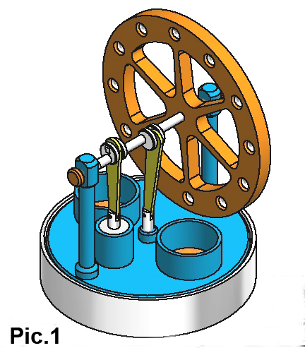
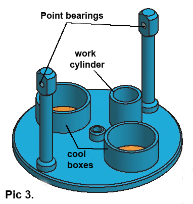
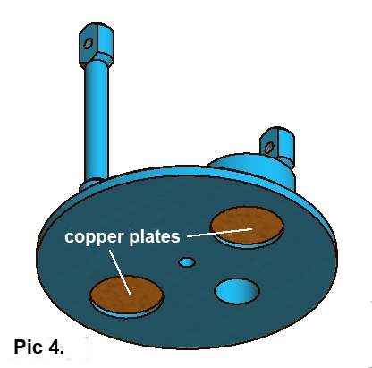
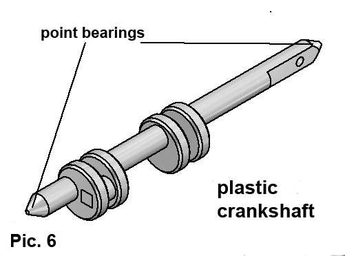
In constant dialogue with Maarten (who lives more than 80 kilometers away from me) we have made the design in such a way that virtually all parts of PLA plastic can be printed and also that the parts are "integral" with what I mean that they are as much as possible made out of one piece. The latter means that there are far fewer separate parts than if the model were made of metal. Apart from 3 copper plates and 12 steel balls in the flywheel all parts are made of plastic, in total only 12 pieces. The most spectacular parts with regard to function integration are the upper structure (Pictures 3 and 4) and the crankshaft (Picture 6).
The special facilities.
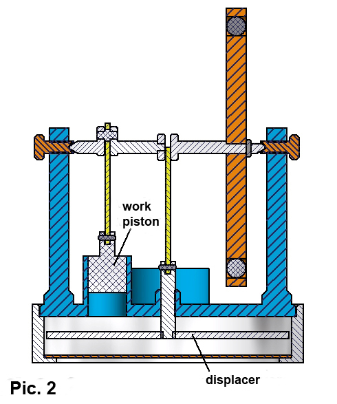
The principle of a Stirling engine is based on the fact that a closed amount of air in the system is cyclically warmed up and cooled down again. This causes pressure fluctuations that cause the working piston to move up and down, resulting in the power of the engine. The heat is supplied from outside to the space under the displacer that moves up and down with some space in its cylinder. The idea is to put this engine on a coffee cup that is filled with hot water so the plastic parts will not be much warmer than about 50 Celsius according to my experience and the PLA plastic will easily survive that in my opinion.The cooling of the air takes place in the space above the displacer as it has pushed the air upwards along the gap between the displacer and its cylinder.
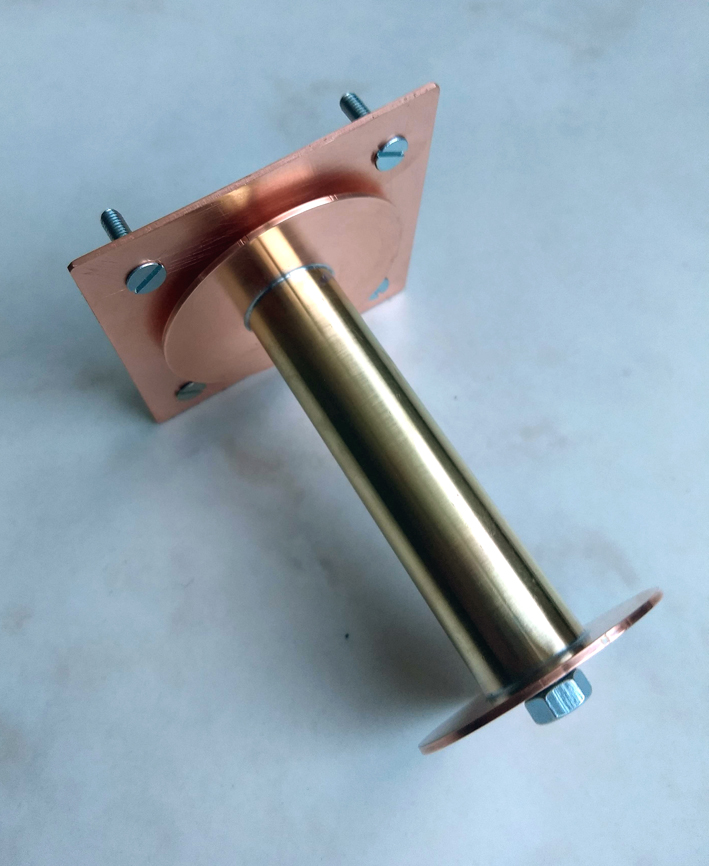
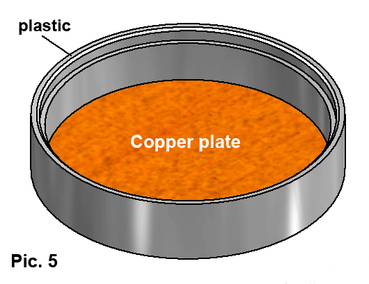
Plastic is a poor thermal conductor, which makes it difficult to heat up and cool down the air again, so that the engine can not run without a special facility. This problem has been solved in this design by gluing a thin copper plate in the bottom of the cylinder for the displacer with transparant silicone sealant to transfer the heat well and smaller copper plates in the two printed coolers on the upper structure to increase the cooling, see the Pictures 3, 4 and 5. Some small ice cubes in those coolers will drastically increase the cooling effect, something that I have experienced with other of my Stirling engines.
The power of such a low temperature Stirling is relatively small, which is why mechanical friction of the system must be kept to a minimum. That is why the crankshaft rotates with very low friction in point bearings as they also are used in small clocks and watches.
Two other places where friction occurs are at the working piston in its cylinder and at the axis of the displacer in its sliding sleeve at the center of the upper structure, see the cross-section in Picture 2. It is contradictory that the fits there must be virtually airtight and on the other hand cause the lowest possible friction. To make this happen, we have made the inner diameter of the working cylinder and that of the sliding sleeve a fraction undersized and then clean them up with machine reamers until the desired result is achieved. This is a tried and tested method for metal parts, but whether this will produce the same good results with plastic practice will prove, but for now I am quite confident about that.
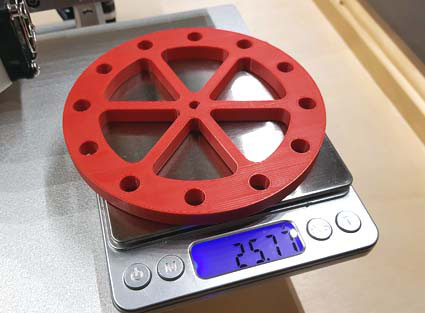
The specific gravity of plastic is relatively low, which is why we will press steel balls with a diameter of 8 mm in the outer circumference of the flywheel, see Picture 1.
Logbook.
All of the above is for the time being only based on experiences and expectations. Practice will have to show to what extent these work out in practice. We will log step by step the making process in this logbook and add something to it every time something has happened that is worth mentioning.
November 23, 2018.
The construction drawings are complete and Maarten has made the 3D models of my drawings that are needed for controlling his 3D printer.
November 25, 2018.
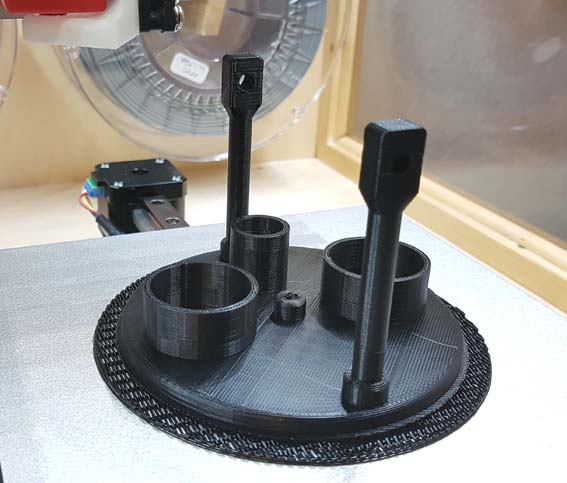
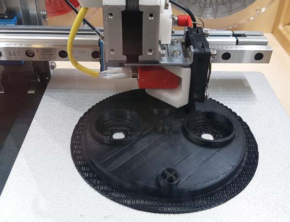
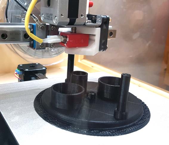
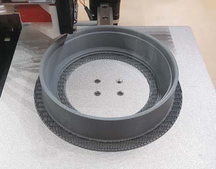
Maarten has started energetically and has already printed the complex upper structure, see the pictures below of several stages of this printing process.
November 28, 2018.
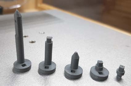
Maarten goes like a spear! (as we say in Dutch). Now he has also printed the cylinder for the displacer and the crankshaft parts, see the pictures below:
December 12, 2018.
There were some little problems with 3D printing: sometimes not loosing properly from the bottom plate or release during printing and some varying qualities of the layer structure on the outsides. There are several parameters that can influence this and Maarten is still figuring it out, but he will managing it as I can see it. One of the causes seems to be the suspension of the reels with the plastic wire. A wooden hook that probably causes too much resistance. I have now made a metal suspension roller with flanges that run on ball bearings. See the picture below:
It runs almost without friction but still needs to be shipped from Roosendaal to Waalre.
December 12, 2018.
Maarten has printed all parts now and put them together loosely, see the pictures below:
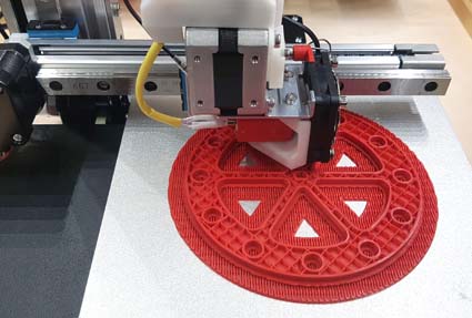
Fly wheel printed half-way
----------------
-Fly wheel ready
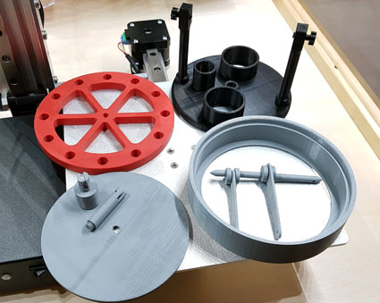
All printed parts
-
Everything loosely put together
It looks super nice. Everything must travel some 80 kilometers from Maarten (in Waalre) to me (in Roosendaal) to put it together definitively and to get this very special engine working. I am very curious, it's up to me now.