"Thermo Pulse Mobile"
The Idea
Surfing on Internet I found a strange little engine called a "Lamina Flow Engine", which looked like as some variant of a Stirling engine. However it simply consists of one piston and a plug of steel wool, both in a glass test tube. It had no displacer and only a single drive connection between the piston and its flywheel. All together it was a remarkably uncomplicated design, at least as far as its appearance is concerned. The description was rather brief but at least the video-clip proved that this engine really runs.
Because I had no real project going at the time I decided to design and make something like it, considering it as a "quickie" project. I got the idea to add a gimmick, giving this thing somewhat more eye-catching appeal. Therefore I planned to design the engine so that it could turn itself around on a central axis on a wooden base. Although I had some doubt that the power of this engine's power would be sufficient for this I thought it was worth while to accept the challenge.
During the designing and building process my pleasure and optimism was growing gradually and the feeling that it was a "quickie" disappeared. I was especially intrigued by the mysterious thermodynamic process in the glass tube in the moments when the first piston strokes occurred. I was also completely suprised by the fact that the power appeared to be more than enough to swing the whole engine around its central axis with a distinguished tempo of 10 rpm!
Video's:
The working principle
Here I can be brief and unfortunately rather vague too:
What happens in the glass tube at the present is not quite fully understood, at least nowhere it is described with full agreement, as far as I know. I can say this because I had an unpretentious participation discussions among the members of the Yahoo HAES Group; people who discuss questions about energy and thermodynamic processes.
Initially it was thouht that the process had a significant resemblance to thermoacoustic engines, a rather well understood and documented process, with patents from the 1950s with theoretical and experimental descriptions. We are confident now that there is another process going on here, i.e. because the tube is far to short for such a thermoacoustic process.
The most recent conclusions lean toward similitarities with the Termal Lag Theory, proposed by Peter Taylor.
So I can only descripe what I broadly think happens, supported by the mentioned discussion partners:
In the glass tube, pressure waves occur that come in resonance with the piston/flywheel system. During a complete cycle, the air in the tube is alternately heated and cooled as it passes between the hot portion of the tube and the cooler cylinder. Apparently this cycling between hot and cold results in a net energy and is enough to keep the piston movement going. The steel wool plug enforces this process, but its exact role is still one of the riddles. From my several experiments and observations there is evidence that the wool has no cooling function, as was previously assumed. The only cooling place seems to be in the piston/cylinder area.
The fact that one will find very different names for this type of engine, such as Thermoacoustic Engine, Lamina Flow Engine, Pulse Tube, Mystery Engine, Moteur à hystérésis thermique, etc. enforces the fact that there are more unproven ideas than hard facts.
I gave my design the unpretentious name of : "Thermo Pulse Mobile"; Thermo Pulse to cover the global process, Mobile because the engine moves itself around.Typical characteristics and sensitivities of this design.
1. The restriction.
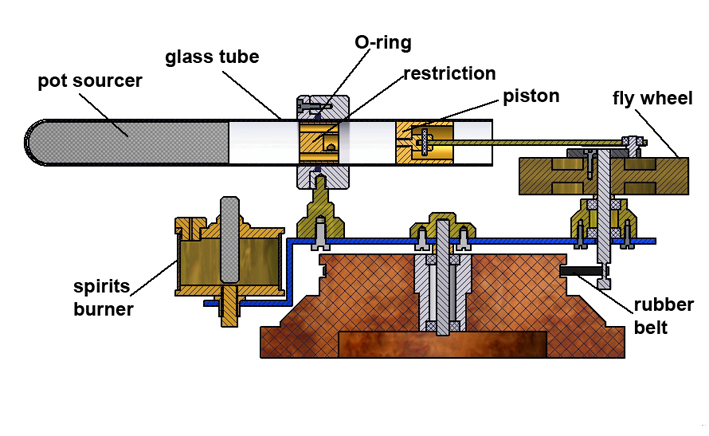
The fact that the true process is not well known creates surprises if one deviates from a working model. I received such a surprise when I applied one solid glass tube in stead of a brass cylinder, sealed in a glass tube with O-rings as I saw in the video-clip. So in my case the glass tube is also used for the cylinder as well. This had consequences for both the temperature and the dynamic pressure within the system.
The fact is that my engine initially did not have any sign of life, with or without the load of rotating the engine. After a lot of random experiments, which I shall not enumerate here because of their irrelevance, I almost gave up until I took a closer look at the video. I noticed a kind of restriction at the place were the brass cylinder was fixed in the glass tube. Although later I discovered that this was only a part of the mechanical construction, at that time I had assumed that this restriction was of some relevance for the system's operation. Because I hadn't the slightest idea how the restriction should look, I used numerous small brass cylindrical plugs from my scrap box, including those with and without all kinds of bores in them and other deformities. I started random experiments, putting al kinds of plugs in the glass tube at the place where it is fixed in the stand; see cross section above.
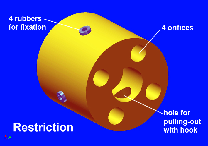
By far, most of the plugs didn't bring any positive effect, but with some of them the engine started to show some sign of life. I was pleasantly surprised and at the same time extremely astonished when I found one plug that caused the engine to keep running, although yet not fully reliable. Using the typical characteristics of this "reference plug" I made a new plug, adding step by step changes to the geometries of the reference plug. This was still a random way of working, but at least somewhat more systematic. Finally I succeed in making a restriction that allowed the engine to run well and reliable; see the picture below:
2. The position of the restriction.
I found that the gap between the restriction and the piston appeared to be very important: the engine runs best if this distance is as close to zero as possible! The best way to adjust this is to push the restriction into place using the piston itself by turning the flywheel manually one turn after the restriction is put in the glass tube. The pressure of the four small rubbers is enough to keep the restriction in place, but is low enough to slide the restriction when the piston pushes it. The result is that the distance between the restriction and the piston is practically zero. Here again I have no undisputed explanation, other then that it is plausible that the dead space in the piston area must be as small as possible.3. The steel wool.
For the steel wool I used the well known household steel scoucer. The scoucer's structure does not seem to be a big influence. The course material has some advantages because the chance for loose steel hairs that can bind the piston is almost zero. I did some experiments with the wool trying to understand its function. One experiment was to cut the wool in two pieces to avoid thermal conduction through the material, assuming that the wool should have a cooling function at the closed end of the tube. The effect was contrary from what expected: the engine was completely dead! So, for me, the one astonishment was placed upon the other. Finally, I came to the conclusion that the tube must be filled completely between the tube's closed end and the place where the spirits flame heats the tube.
4. The position of the spirits burner.
Here again a single-valued conclusion without clarification: the flame must be exactly on the interface wool-to-air; see the cross section above. Every other position results in a poor and mostly non functional engine! The flame must be rather large and somewhat "washing" around the glass tube. Apparently the tube must be rather hot with this design to produce enough power in the engine.
Although the engine is swinging around with rather low speed, the spirits flame can be somewhat blown away from the glass tube due to the rotation of the engine. To prevent insufficient heating of the tube the wick must be pulled away a little bit, opposite to the swinging direction.
5. The piston fitting
A very small clearance of the piston in the glass tube is important for a good performance of the engine: equal or smaller than 0.05mm. That means in the first place that you must obtain a glass test tube that is very well cylindrical with a diameter variance of less than 0.03mm, at least over the area where the piston is moving. Not all glass tubes fulfil this requirement! Of course there must be always some clearance because the piston must move in the tube with very low friction.
The construction
As one can see on the sketch and drawing plan the construction of this design is very simple so that it needs hardly any further explanation, except:
1. The inner diameter of the glass (Pyrex) tube must be fairly cylindrical within some hundreds of a mm. Not all test tubes will fulfill this requirement but they do exist, eg pyrex Duran (Fiolax) heat resistant test tubes.
2. There must be a good seal between the piston and the cylinder, on the other hand the friction must be as low as possible. For that graphite is the most ideal material also because the thermal expansion is about the same as the Pyrex glaas of the tube. Less ideal is that the availability of graphite can be a problem. If one cannot obtain graphite the piston can be made from brass as well if you make it also well fit in the glass tube and if you polish the brass surface. The thermal expansion of brass is about 5x greater than that of Pyrex glass, but that is not an objection because the temperature of this piston will become hardy any higher than the ambient temperature. In fact it is my experience that with such a brass piston the engine will run as good as with a graphite piston.
3. The rubber belt must be thin and flexible. Although not very critical, the belt's perimeter (about 30 cm) must be so that it can be stretched lightly around the groove in the wooden base and around the flywheel axle.Starting up the engine
The engine can be started about 30 seconds after lightening the spirits burner. After reaching the operating temperature, a light push on the flywheel is sufficient to start the engine. The engine has no preference for the rotation direction.
If everything is adjusted properly this engine runs reliable and perfectly with a flywheel speed of about 600rpm. Because the reduction ratio is 1 to 60 the entire engine swings with a speed of about 10 rpm around its central axis. Without this load the engine has a speed of about 900rpm.Drawing Plan
I made a CAD drawing plan for this Thermo Pulse Mobile that is available for every one interested; click here for a request.Finally
I want to thank Stephen Winslow for screening my "Dutch English", not making you think that my English is perfect, but to avoid misunderstandings.


Very nice work-out by
Jeroen Jonkman:
Nice replica by Rick Giordano:
Nice replica by Claudio Mercuri
Nice replica made by
Daniel Salmeron Ballart:
Replica Paul Iriks: