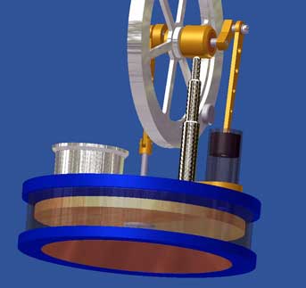
The objective of this project
On Internet I found some low-temperature Stirling motors, claiming that they can run on the warmth of a human hand. I put myself to aim to, at least, equalize this achievement by optimizing my Coffee-cup Stirling model nr.9 to such an extend that I should accomplish this challenge successfully.
The approach
It should be clear that a human hand can add only very few energy to the system. Despite it, this low energy has to overcome the counteracting forces to get the Stirling running. So the the challenge is to eliminate this forces to such an extend that the energy of the hand warmth conquers.
In this case there are two counteracting forces:
1. The gravity force, working on the a-symmetric system with displacer, working piston, driving rods and crank webs. In principle these gravity forces can be eliminated for nearly 100% by accurate mechanical balancing.
2. Mechanical frictions, working on rotating and sliding parts. We will neglect the friction of air on mainly the flywheel in this case.
It is not possible to eliminate frictions completely. He who claims he can do so is inventor of the perpetual mobile and will be immortal all of a sudden! So we can only strive to eliminate this frictions as much as possible. The better we succeed in this the better the engine will run on the hand.The working-out
Ad.1: Eliminating the gravity forces.
It is important to balance the system without the hindrance and influence of atmospheric pressure variations in it. Therefore this equilibration must be done with everything assembled except for the bottom cylinder plate, thus with the open system. Balancing can be done in different ways. I choose for a counterweight on the circumference of the fly wheel.
This balancing procedure goes as follows:
- First oversize the thickness of the counterweight somewhat so it can be turned off step by step to the right weight;
- Push the fly wheel without counterweight lightly and wait till it stops. With that crank shaft position turn the fly wheel so that the hole for the counterweight is on top.
- Fix the fly wheel and indicate its relative position to its axle by making bench marks with opposite scratches on the fly wheel kernel and the axle. With that it will be possible to find back the right relative position of the fly wheel to its axle in case it may be distorted later;
- Put the over-sized counterweight in the hole of the fly wheel and push the fly wheel again. Because the counterweight is too heavy the system will stop with the counterweight somewhere below. Now the counterweight must be turned-off step by step a little until the system stops with an entire random position of the counterweight. A somewhat time consuming job but important to achieve the elimination of the counter-action gravity force and, with that, a minimum required temperature difference to let the engine run.
Ad.2: Minimizing the mechanical frictions.
-Just as on the flywheel axle I applied small ball bearings in the big ends of the two driving rods. It is my experience that it is important to clean the ball bearings with some dry cleaning spirits, without greasing them after wards. Greasing may be good to prevent wearing, but this is not relevant in this case. With dry and grease free ball bearings the friction is very low.
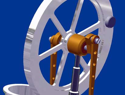
-To prevent cross forces I placed the cam webs on both sides of the flywheel bearing. The two pivots on the crank webs must be perfect rectangular to these webs to prevent torsion of the driving rods while turning. For the same reason the center lines of the driving rods must coincide exactly with the center lines of the two cylinders.
Remains the friction of the working piston in its cylinder and the displacer axle in his slide bearing. For the working piston I used graphite as material. You can make this graphite extremely smooth polishing it with a piece of a newspaper between thumb and forefinger, turning the piston around in the lathe. Graphite is excellent self-greasing, which is important since this working piston never may be lubricated, how thin the oil is!!
For the same reason I made the glide bearing for the displacer rod from graphite also, making the bore a fraction undersized and then ream it to H6 precision diameter. The displacer rod is made from standard material that you can buy everywhere. The diameter is precise and smooth, better than you (me) can make it yourself. This rod moves almost air-tight and with very low friction in the graphite bearing. It is my experience that you rather allow a very small leak rather than too high friction.Finally:
- I made the displacer from the very light but stiff Balsa wood with an aluminum kernel in what the displacer rod is screwed. If wanted one can use polystyrene instead off Balsa wood.
- I glued a 1mm thick copper plate in the bottom plate for a better and faster conduction of the hand warmth to the air in the system. The final maximum temperature will be the same as with a solid aluminum bottom plate.With this set of measures I succeed in making a small Stirling engine that can run with a temperature difference between upper and bottom cylinder plate of about 11 to 12 ºC, a tremendous improvement compared to the original Coffee-cup Stirling which needed 40 to 45 ºC temperature difference.
The performance of this engine
The graph below shows the relation between the temperature difference (x-axis) between the upper and the bottom cylinder plate and the revolution speed (y-axis) of the engine. For this measurements I placed the engine with the bottom plate in a sheet of water with a starting temperature of about 50 ºC. I could measure this temperature exactly and easily during cooling down with a mercury thermometer. The temperature of the upper plate was constant and equal to the environment temperature.Video:
The conditions for running the engine on the hand
The taken measures as such are no guarantee that this engine will run on the hand under all conditions, because the temperature difference of at least 11 ºC always must be attained. The surface temperature of a human hand can vary sorely. On a cold hand, which you can have after a outside walk in the winter, the temperature of the bottom plate becomes not more than 22 to 24 ºC; on a normally warm hand you can reach 28 to 30 ºC max. But even then the engine will just fail if the room temperature (=engine temperature) is higher than about 19 ºC. Putting the engine in a cold place for a while solves the problem, but it is easier to put a half ice cube in the little aluminum box that can be placed on the upper cylinder plate. May be this is more or less a "kill or cure" remedy, but it is efficient ! With these secondary measures the engine starts running easily as long as the temperature difference stays 11 ºC or more. With this little piece of ice this engine will run at least half an hour on your hand which is generally spoken too long to withstand muscle cramp in your hand !
At higher temperatures as they occur when the engine is placed on a cup with hot water a revolution speed of 400 to 600 rpm can be reached. The run time varies from 1 to 1½ hour, depending on the size and isolation properties of this cup. With a small piece of ice in the metal box on the upper plate this runtime can be enlarged significantly, because it reduces the inevitable warming-up of the upper cylinder plate.Of course the ultimate challenge is to eliminate the trick with the ice cube. But to realize that it is necessary to decrease the required temperature difference of 11 ºC with some centigrade's. In my opinion this only can be obtained by reducing the frictions substantially. I have reasonable doubt that I will succeed in this, but I will try; you never now !
Drawing plan
For this Low Temperature Stirling I made a CAD drawing plan; click here for a request.


