Introduction.
Normally a 4-stroke engine has two valves in the cylinder head, one for the intake of the gas mixture from the carburetor and one for the exhaust of the burnt gases. The system for driving these spring-loaded valves usually consists of two cams on a driven shaft with valve lifters and rocker arms connected to them. I did use this system for a number of my 4-stroke engines, but although it is certainly feasible, it is still quite complex and it also causes some shock loads on the running engine.A system with a rotating inlet and exhaust valve.
I assumed that a rotating valve would be much simpler because it would eliminate the up and down valves and therefore also the entire drive system for them. My first attempt at this consisted of two flat ground metal discs that were pressed together with a disc spring. The stationary disc had an inlet and exhaust opening and an atmospheric coupling at the top of the cylinder. The bores in both discs were positioned opposite each other in such a way that the intake and exhaust took place at the right moments in the process cycle. I did get the engine running with this, but it still caused a problem that was difficult or impossible to solve: the high combustion pressure during the working stroke of 15 to 20 atmospheres regularly pushed the rotating disc away from the stationary disc, causing a fatal gas leak to the outside air. To solve this problem, I came up with the idea of ??making the stationary part of such a valve from a bronze cylinder in which a round steel mandrel with a precise h6 fit could rotate. The steel mandrel is thus completely enclosed in the bronze housing, so that it cannot be pushed away from the bronze housing by the high combustion pressure. This would also make pressing with some kind of spring system unnecessary, making the valve system extremely simple. In my humble opinion, it couldn't be much simpler.The principle of this "Ridders 4-stroke engine".
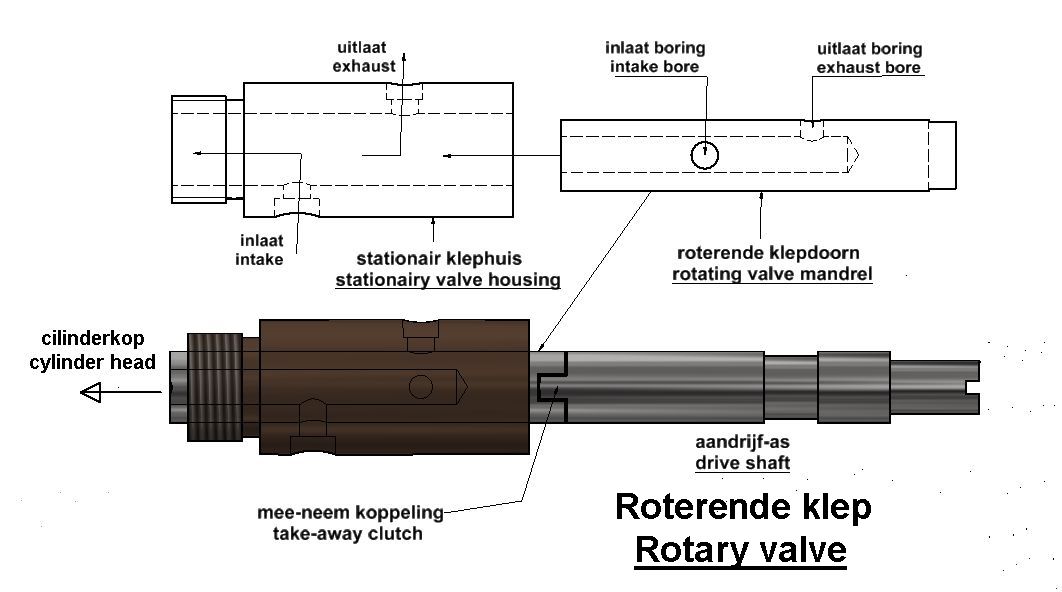
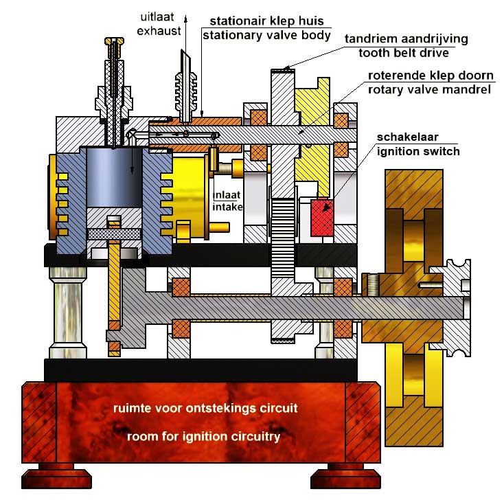
The CAD figure below illustrates the rotary valve system as I made it for this 4-stroke engine.
The shaft that drives the valve stem is connected by a toothed belt to the crankshaft that drives the piston with a transmission ratio of 2 to 1 as is always the case with a 4-stroke engine. I deliberately chose not to make this shaft and the valve stem from one piece because the centre line of the valve stem and that of the bronze valve housing would then have to be exactly in line with each other. A small deviation from this would immediately cause unwanted friction between the valve stem and the valve housing, resulting in wear or even seizing. I therefore used a "take-along" construction in which a rectangular "lock" on the drive shaft fits with some space in an equally rectangular slot in the head of the valve stem. The valve stem has two separate cross-bores on the circumference that both end up in a central bore in the stem that is therefore constantly in atmospheric connection with the cylinder. These bores connect the bores in the valve body at the right moments for the intake of the fresh gas mixture and for the exhaust of the burnt gases. In between, the openings in the valve body are blind during the compression and combustion strokes. Thus, the 4-stroke process is completely and implicitly determined by the geometries of the bores in the valve stem and those in the stationary valve body; see the animation below:
Note: When making the above animation I had made the drive shaft and valve stem from one piece.
The cam disk for the switch that controls the spark at the moment of maximum compression is also located on the drive shaft of the valve mandrel. As with all my combustion engines, I have again used my Petrol Vapor Carburetor here, which is connected to the inlet of the stationary valve section with a rubber hose. For adjusting the Petrol Vapor Carburetor, see the instructions on the last page of the drawing package. Adjusting the engine Adjusting the engine is extremely simple. It comes down to having the start of the intake coincide exactly with the (first) highest position of the piston. If this is set this way once, the other process settings are automatically correct because they implicitly follow from the relative geometries of the bores in the rotary valve. Setting this intake moment is done as follows:
1. Unscrew the gear on the drive shaft of the valve mandrel so that it can rotate freely there and place the piston in its highest position by .
2. Remove the spark plug and put a rubber hose on the inlet connection of the stationary valve housing where the carburetor is normally connected.
3. Blow through the hose with your mouth and turn the valve mandrel clockwise until air is just audible escaping through the spark plug hole.
4. In this position, screw the gear back onto the drive shaft of the valve mandrel.The pattern of the holes in the valve is made in such a way that the start of each of the four strokes (intake, compression, ignition and exhaust) coincides exactly with the four extreme positions of the piston. This "straightforward" setting is not only the simplest but the engine also runs very well and reliably. It meets my eternal aim to keep everything as simple as possible, coupled with high reliability.
The spark ignition.
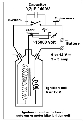
For the spark ignition I use my universal external unit with a spark plug from a (classic) car, see the circuit diagram below
For the power supply I use the rechargeable battery of my hand drill. This spark plug is quite large and therefore does not fit in the foot of the engine. However, there are many smaller ready-made electronic CDI systems for sale on the internet, for example a circuit from Aliexpress that a fellow model builder had a lot of success with, click here for the relevant page. The spark must come exactly at the moment that the piston has arrived in its next highest position, namely at the moment that the fresh gas mixture has been compressed to the maximum pressure. This is a matter of fixing the cam disk in the right place with respect to the switch for the ignition circuit.
Starting up and engine performance
It is best to start the engine the first time with a belt around the pulley on the flywheel shaft and a similar pulley in the head of a hand drill. In doing so, the air regulator on the carburetor must first be fully opened for mixing in extra air and then gradually closed until you hear the engine start. The engine runs best around this carburetor setting and the speed can be regulated somewhat by allowing a little more or a little less added air. The speed of this engine can be regulated between approximately 600 and 1000 revolutions per minute. Relatively low compared to, for example, the Otto engine which can easily run twice as fast with the same cylinder/piston combination. Initially I thought that the rather narrow channels in the rotary valve were the cause, but after some experiments this turned out not to be the main cause. Presumably it has to do with the "half moon" transitions between the bores in the valve which open a bit less quickly than the classic up and down valves of a four-stroke engine, but I don't know for sure (yet). I don't think that's so bad because for this kind of 1-cylinder models I prefer low revs over very high revs where restless behavior will occur.
The engine runs on regular car petrol, but Coleman Fuel is preferable for the following reason: Because the engine has no forced cooling, the cylinder becomes 100 to 110 degrees Celsius warm after about 5 minutes of running. In itself no problem because the piston and the cylinder are made of pearlitic cast iron, which means that there is no question of seizing due to thermal expansion. But the aluminium mounting plate also becomes about 50 degrees warm in the long run and because the brass carburettor is also screwed onto it, the fuel in it is also heated to about 40 degrees Celsius. In itself not bad, but it does affect the vapour pressure in the carburettor. Because regular car petrol contains several volatile components, separation occurs somewhat faster at this higher temperature, which makes the setting of the air regulator somewhat more unstable. Coleman Fuel contains considerably fewer different components and this certainly results in much more stable behaviour in this case.
Drawing plan
I made a CAD drawing plan for this engine that I will send by e-mail to for anyone who likes to build it; click here for a request.
Introduction.
Normally a 4-stroke engine has two valves in the cylinder head, one for the intake of the gas mixture from the carburetor and one for the exhaust of the burnt gases. The system for driving these spring-loaded valves usually consists of two cams on a driven shaft with valve lifters and rocker arms connected to them. I did use this system for a number of my 4-stroke engines, but although it is certainly feasible, it is still quite complex and it also causes some shock loads on the running engine.A system with a rotating inlet and exhaust valve.
I assumed that a rotating valve would be much simpler because it would eliminate the up and down valves and therefore also the entire drive system for them. My first attempt at this consisted of two flat ground metal discs that were pressed together with a disc spring. The stationary disc had an inlet and exhaust opening and an atmospheric coupling at the top of the cylinder. The bores in both discs were positioned opposite each other in such a way that the intake and exhaust took place at the right moments in the process cycle. I did get the engine running with this, but it still caused a problem that was difficult or impossible to solve: the high combustion pressure during the working stroke of 15 to 20 atmospheres regularly pushed the rotating disc away from the stationary disc, causing a fatal gas leak to the outside air. To solve this problem, I came up with the idea of ??making the stationary part of such a valve from a bronze cylinder in which a round steel mandrel with a precise h6 fit could rotate. The steel mandrel is thus completely enclosed in the bronze housing, so that it cannot be pushed away from the bronze housing by the high combustion pressure. This would also make pressing with some kind of spring system unnecessary, making the valve system extremely simple. In my humble opinion, it couldn't be much simpler.The principle of this "Ridders 4-stroke engine".
The CAD figure below illustrates the rotary valve system as I made it for this 4-stroke engine.
The shaft that drives the valve stem is connected by a toothed belt to the crankshaft that drives the piston with a transmission ratio of 2 to 1 as is always the case with a 4-stroke engine. I deliberately chose not to make this shaft and the valve stem from one piece because the centre line of the valve stem and that of the bronze valve housing would then have to be exactly in line with each other. A small deviation from this would immediately cause unwanted friction between the valve stem and the valve housing, resulting in wear or even seizing. I therefore used a "take-along" construction in which a rectangular "lock" on the drive shaft fits with some space in an equally rectangular slot in the head of the valve stem. The valve stem has two separate cross-bores on the circumference that both end up in a central bore in the stem that is therefore constantly in atmospheric connection with the cylinder. These bores connect the bores in the valve body at the right moments for the intake of the fresh gas mixture and for the exhaust of the burnt gases. In between, the openings in the valve body are blind during the compression and combustion strokes. Thus, the 4-stroke process is completely and implicitly determined by the geometries of the bores in the valve stem and those in the stationary valve body; see the animation below:
Note: When making the above animation I had made the drive shaft and valve stem from one piece.
The cam disk for the switch that controls the spark at the moment of maximum compression is also located on the drive shaft of the valve mandrel. As with all my combustion engines, I have again used my Petrol Vapor Carburetor here, which is connected to the inlet of the stationary valve section with a rubber hose. For adjusting the Petrol Vapor Carburetor, see the instructions on the last page of the drawing package. Adjusting the engine Adjusting the engine is extremely simple. It comes down to having the start of the intake coincide exactly with the (first) highest position of the piston. If this is set this way once, the other process settings are automatically correct because they implicitly follow from the relative geometries of the bores in the rotary valve. Setting this intake moment is done as follows:
1. Unscrew the gear on the drive shaft of the valve mandrel so that it can rotate freely there and place the piston in its highest position by .
2. Remove the spark plug and put a rubber hose on the inlet connection of the stationary valve housing where the carburetor is normally connected.
3. Blow through the hose with your mouth and turn the valve mandrel clockwise until air is just audible escaping through the spark plug hole.
4. In this position, screw the gear back onto the drive shaft of the valve mandrel.The pattern of the holes in the valve is made in such a way that the start of each of the four strokes (intake, compression, ignition and exhaust) coincides exactly with the four extreme positions of the piston. This "straightforward" setting is not only the simplest but the engine also runs very well and reliably. It meets my eternal aim to keep everything as simple as possible, coupled with high reliability.
The spark ignition.
For the spark ignition I use my universal external unit with a spark plug from a (classic) car, see the circuit diagram below
For the power supply I use the rechargeable battery of my hand drill. This spark plug is quite large and therefore does not fit in the foot of the engine. However, there are many smaller ready-made electronic CDI systems for sale on the internet, for example a circuit from Aliexpress that a fellow model builder had a lot of success with, click here for the relevant page. The spark must come exactly at the moment that the piston has arrived in its next highest position, namely at the moment that the fresh gas mixture has been compressed to the maximum pressure. This is a matter of fixing the cam disk in the right place with respect to the switch for the ignition circuit.
Starting up and engine performance
It is best to start the engine the first time with a belt around the pulley on the flywheel shaft and a similar pulley in the head of a hand drill. In doing so, the air regulator on the carburetor must first be fully opened for mixing in extra air and then gradually closed until you hear the engine start. The engine runs best around this carburetor setting and the speed can be regulated somewhat by allowing a little more or a little less added air. The speed of this engine can be regulated between approximately 600 and 1000 revolutions per minute. Relatively low compared to, for example, the Otto engine which can easily run twice as fast with the same cylinder/piston combination. Initially I thought that the rather narrow channels in the rotary valve were the cause, but after some experiments this turned out not to be the main cause. Presumably it has to do with the "half moon" transitions between the bores in the valve which open a bit less quickly than the classic up and down valves of a four-stroke engine, but I don't know for sure (yet). I don't think that's so bad because for this kind of 1-cylinder models I prefer low revs over very high revs where restless behavior will occur.The engine runs on regular car petrol, but Coleman Fuel is preferable for the following reason: Because the engine has no forced cooling, the cylinder becomes 100 to 110 degrees Celsius warm after about 5 minutes of running. In itself no problem because the piston and the cylinder are made of pearlitic cast iron, which means that there is no question of seizing due to thermal expansion. But the aluminium mounting plate also becomes about 50 degrees warm in the long run and because the brass carburettor is also screwed onto it, the fuel in it is also heated to about 40 degrees Celsius. In itself not bad, but it does affect the vapour pressure in the carburettor. Because regular car petrol contains several volatile components, separation occurs somewhat faster at this higher temperature, which makes the setting of the air regulator somewhat more unstable. Coleman Fuel contains considerably fewer different components and this certainly results in much more stable behaviour in this case.
Drawing plan
I made a CAD drawing plan for this engine that I will send by e-mail to for anyone who likes to build it; click here for a request.