Introduction.
Earlier I made the Linford 2-stroke engine in which two pistons run against each other in one and the same cylinder. The intake, exhaust and spark plug are by definition in the middle of the cylinder in such engines because that is also where the common combustion chamber is located. The space to make an intake and exhaust system there for a 4-stroke engine with an intake and exhaust valve, including the drive mechanism with rockers, tappets and cam discs is so small that it is very difficult if not impossible to realize this there. That was also the reason why my Linford became a 2-stroke because it has no intake and exhaust valves at all. In the meantime I have gained experience with a number of new substructures with my later combustion engines. A number of them now make it possible to make a 4-stroke version of such a "duo piston engine", in which the intake and exhaust are very easy to realize in the middle of the common cylinder. In particular, the very simple and compact rotary valve that I used in the "Ridders 4-stroke" gave me the idea to design and make such an engine now. For reasons that I will explain later, I have chosen to use this rotary valve only for the exhaust process and to make the intake itself suction by using a small and simple ball valve that I also have good experiences with.
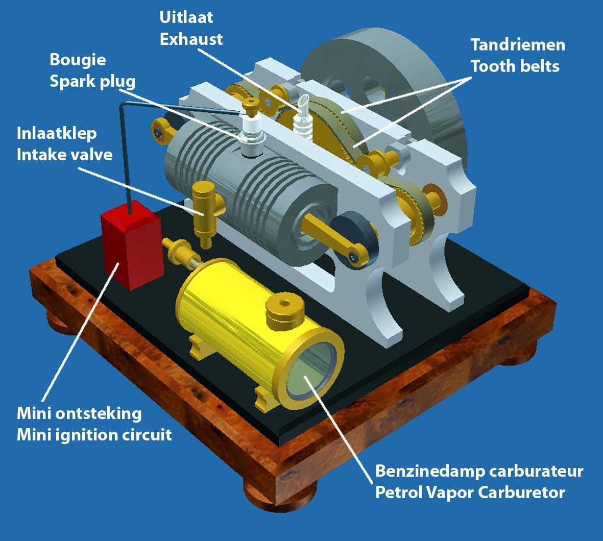
I finished the CAD drawing plan for this concept as per October-20-2011. The Cad pictures below illustrate the construction:
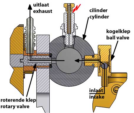
Cross section of the valve system
Some characteristics:
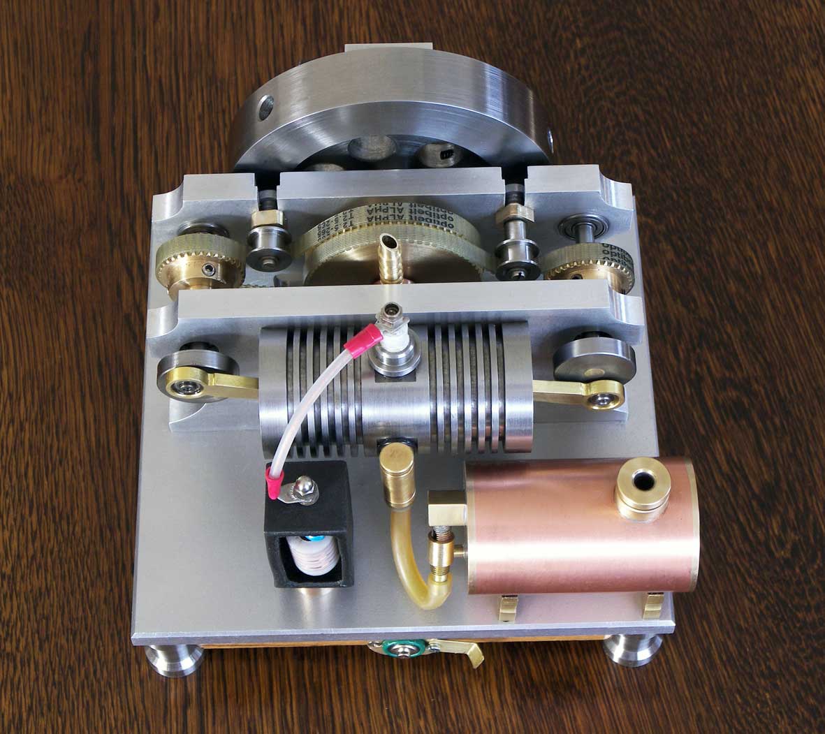
1. I have chosen a horizontal position of the entire system because this results in a compact and stable construction.
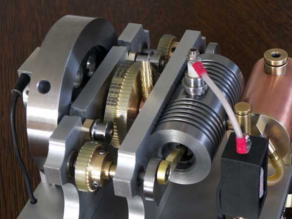
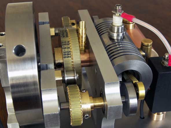
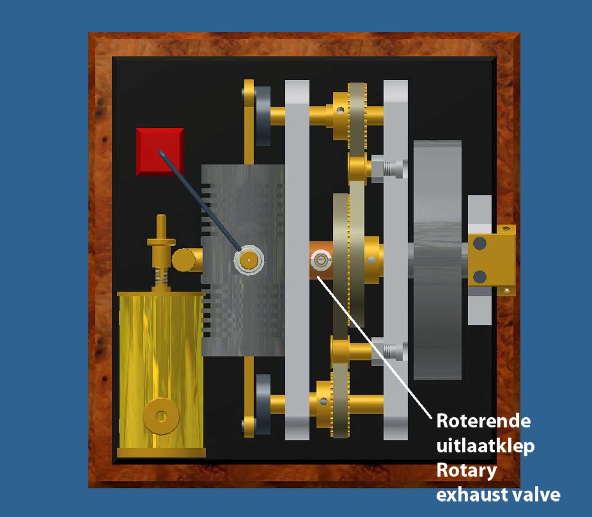
2. Again, I use toothed belts for the drive for the reasons I mentioned earlier: great freedom of construction, smooth and silent without any lubrication. It is possible to use only one toothed belt over the three toothed wheels, but in this case it turned out to be difficult to get it to engage over sufficient circumference of mainly the central large toothed wheel. I have therefore chosen to use two separate and narrower toothed belts: one for one and one for the other crankshaft. They both run over the same central toothed wheel that is on the shaft of the rotary valve with a distribution ratio of 1 to 2 that is required for every 4-stroke. This larger toothed wheel is therefore twice as wide as the toothed wheels on both crankshafts. Two tension wheels ensure the correct belt pressure and their upright sides keep the belts in place in a horizontal direction.
3. Although it is possible to make the rotary valve suitable for both intake and exhaust (as I did with the "Ridders" engine), I have chosen here for only exhausting with that rotary valve. The valve could be somewhat shorter so that the construction becomes more compact and the crawl paths in that valve are also more favorable, which further reduces the chance of leaks. In fact, it is also not necessary to regulate the intake with this because the engine itself can just as well suck in the fresh gas mixture from the carburetor via a single ball valve on the cylinder head. Such a valve remains automatically closed during the compression stroke, the combustion stroke and the exhaust stroke and also opens automatically if there is negative pressure in the cylinder during the intake stroke of the pistons.
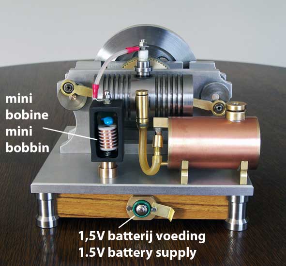
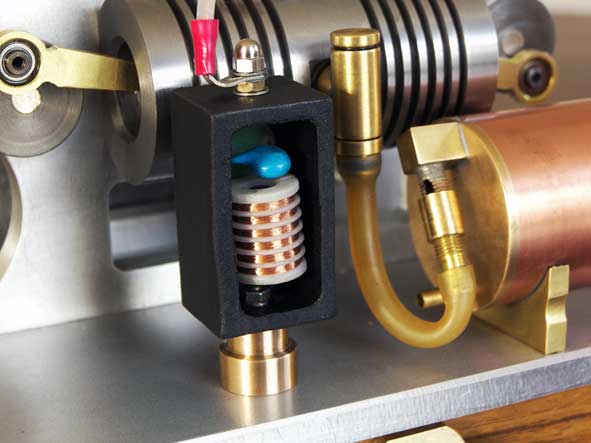
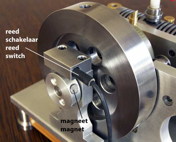
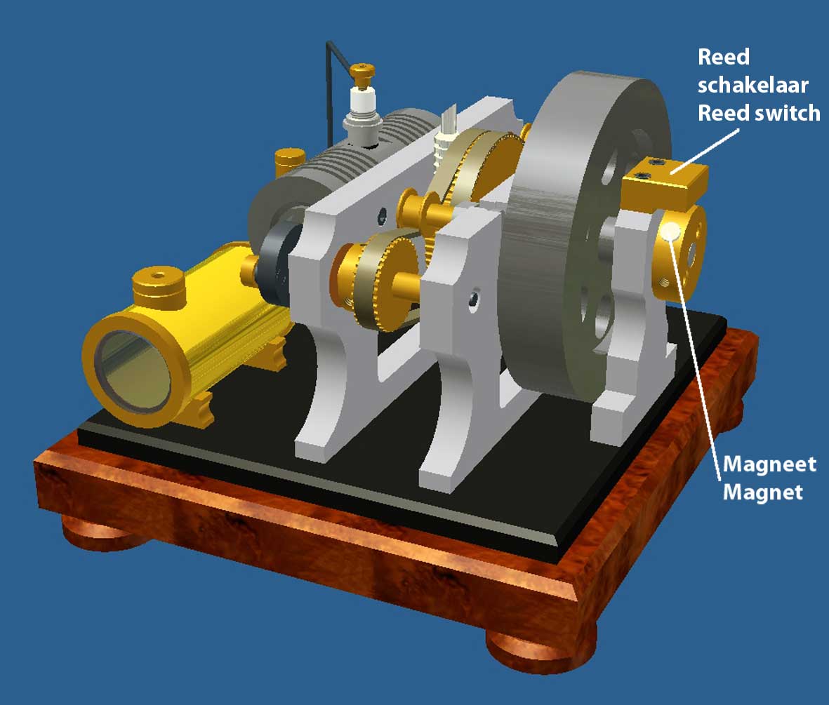
4. For the spark ignition I use the super small circuit from the Blokker gas lighter. A small Neodymium magnet in the starter pulley on the flywheel axle switches a reed contact for the spark ignition at the right moment in the process for which that pulley has to be fixed once in the right place on its axle. Not everyone will have such a circuit but every model builder of this kind of engines has his own solution for making sparks I assume.
A compilation of useful "tricks" from the past".
This has become a unique and relatively very simple 4-stroke engine, if I may be so bold as to say so. It is, as it were, a sum of almost all the useful tricks that I have used in the last few years on various of my other models, such as:
- Two pistons running against each other in one cylinder with a shared combustion chamber in the middle of the cylinder. One of the advantages is that this eliminates the cylinder heads. I don't really know whether that is more efficient, but it is at least funny to see.
- Very simple mechanisms for the intake and exhaust process, with an automatically operating ball valve and a rotating valve respectively. Adjusting the 4-stroke process is very simple and only involves positioning the rotating mandrel in the exhaust valve on the flywheel axis once.
- Simple single-sided and external crankshafts for the pistons with matching connecting rods; no crankcase.
- A super small and home-made system for the ignition of the spark on the home-made spark plug. A small Neodymium magnet in the starter pulley controls a reed switch for the spark at the right moment in the process. The control current through the very fast reacting reed contact is so low that the life of the reed switch will be almost "infinitely" large. The single spark thus in fact ignites the gas mixture above both pistons simultaneously so that no spark distributor is needed and/or a double coil system;
- No forced cooling and/or lubrication, mainly by using pearlitic cast iron for the cylinder and the pistons. Provided that the pistons are made to fit accurately in the cylinder, piston rings can be omitted without any problem. Not only easier but this also greatly reduces the friction of the pistons in the cylinder;
- Application of the problem-free Petrol vapour carburettor.
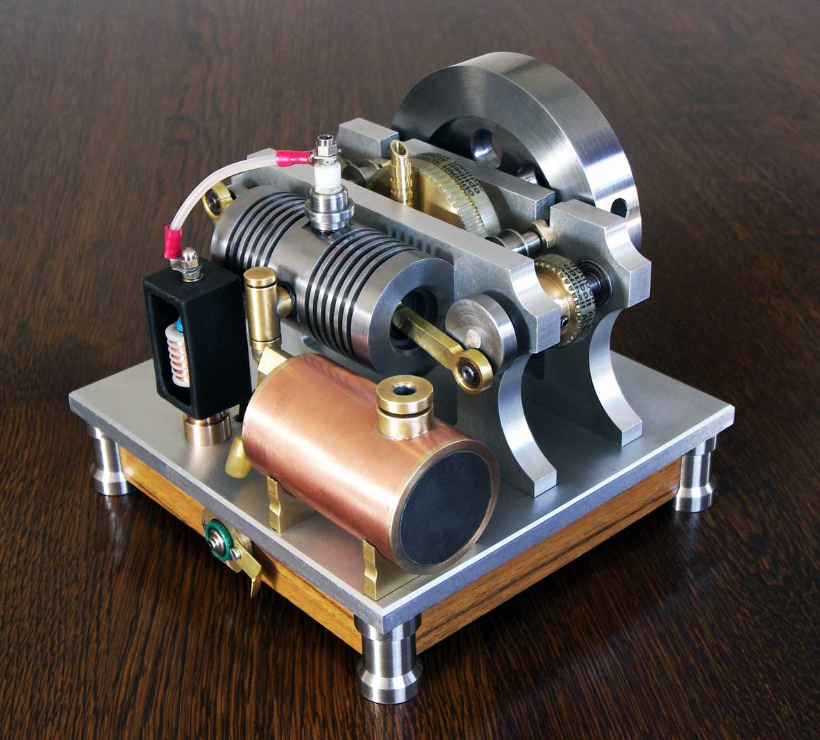
The result
The engine is running perfectly with adjustable speed between 600 and 1100 RPM; see the video below:
Drawing plan.
I made a CAD drawing plan for this engine that is available for any-one interested, click here for a request.
************************************************************
Hints in case of troubles
The ball valve.
- Check the free vertical stroke of the ball against the screwed-in stop pin above it. This stroke should not be much more than approximately 0.5 mm because otherwise there is a chance that the ball will float or bounce.
- Check for air leaks: Put a rubber hose over the connection above the ball. Immerse the valve in water and blow into the hose with your mouth. There should then be no clear air bubbles visible in the water. After this test, immerse the valve in e.g. white spirit and blow the valve dry internally.
The rotating exhaust valve.
It is important that the rotating steel mandrel fits cleanly and virtually leak-free in the bronze valve housing. That is why I always use a standard silver steel axle for the mandrel in such a case because this has always the perfect size with an even and very smooth surface. First make the bore in the bronze valve housing slightly undersized and then clean it up with an H6 reamer. This way the mandrel will rotate in the valve housing with low friction and almost perfectly leak-free.
The cylinder and the two pistons.
The pistons (without piston rings) must of course also fit almost leak-free in their joint cylinder. Honing is perhaps the best way to make a cylinder bore nice and cylindrical and smooth. However, most model builders like me often do not have the equipment for this. That is why I myself always do it as follows and with good results:First roughly drill out the cylinder hole and then turn it out to the desired diameter with approx. 0.1 mm undersize. Then manually ream the hole with an adjustable reamer because it will then search for itself in the cylinder bore. Clamp the reamer in a vice with the flat end of the cone, so do not turn the reamer but the cylinder manually over the reamer in the vice. Always add plenty of oil. When reaming, turn the cylinder several times with the same reamer setting until it runs smoothly through it. Then repeat this procedure with the reamer set a fraction larger. Repeat these operations until there is actually no more measurable difference in diameter over the entire length of the bore, which will then also be nice and smooth. The diameter that is then created does not have to be exactly the same as that shown in the drawing because the piston is only made to fit in the cylinder after this, as follows: Turn the piston until it fits somewhat "hooking" in the cylinder. By manually polishing the piston in the cylinder with a fine abrasive paste (e.g. car cleaner Commandant nr.4). This creates a fit with a clearance of 0.02 millimeters or even less! The result is that the friction is so low that the engine rotates "as if driven by the wind" while there is more than enough compression, even without piston rings.
This method of making the cylinder bore is very similar to honing and with a bit of patience it is hardly or not inferior to it. In any case, it works well with pearlitic cast iron (GG25) mainly because this material is somewhat sandy and is therefore easy to work with. This material is nevertheless very wear-resistant, is somewhat self-lubricating due to the relatively high carbon content (approx. 8%) and does not tend to corrode when the piston moves up and down in it. Now there is also a chance that you do not have an adjustable reamer. It can also work very well if you turn the cylinder hole nice and smooth with a sharp internal chisel, whereby you always have to turn from the outside to the inside with the lowest feed rate. The last time, turn the chisel away from the material before you retract the chisel. If the lathe is properly aligned, the hole will also be nicely cylindrical (less than 0.02 mm taper). If not, ream the hole with a low speed reamer and ream oil, then polish the piston in the cylinder as I described above.
One-time adjustment of the rotary exhaust valve relative to the piston positions.
See the instructions for that on page 9 of the drawing package.
Adjusting the carburetor.
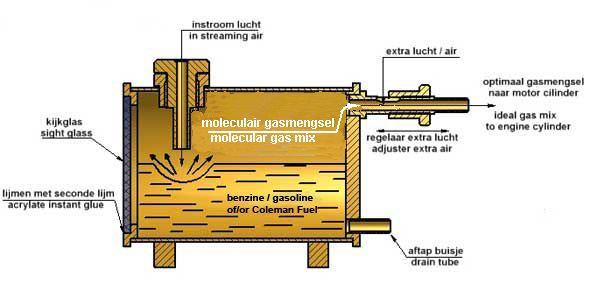
During the intake stroke of the engine, the gas mixture in the carburetor tank is sucked into the cylinder via the automatically opened ball valve. The ideal gas mixture for complete combustion should contain 1 part fuel to approximately 14 parts air. However, the primary gas mixture above the fuel in the carburetor contains too little air for this, which means that extra air has to be added. This is done through a slot in the exhaust pipe on the back of the carburetor. With a slide with a screw thread in it, the slot can be covered to a greater or lesser extent so that the correct amount of extra air can be set. For a one-time adjustment of the slide, it is best to proceed as follows:
- Place the slide in the position where the slot is fully open. In that position, too much air is added, which means that the engine will not run or will not run properly;
- Gradually screw the slider further over the slot while starting the engine (for example with a hand drill machine) until you hear the engine start-up;
- In that position of the slider, the composition of the gas mixture that is sucked into the cylinder will be ideal, which will ensure that the engine runs optimally and very reliably. Around this setting of the slider, the engine speed can also be varied within certain limits.
PS. For a detailed description of this "Petrol Vapour Carburetor" click here.
"********************************************************
<