Introduction
After I had built three 4-stroke and also three 2-stroke engines, I came up with the idea of building a so-called "hit&miss" 2-stroke engine. Hit&miss engines are actually always 4-stroke engines. The typical feature is that by means of a centrifugal mechanism on the flywheel, the movement of the exhaust valve is blocked at a certain high speed, causing the exhaust valve to remain open for a while. At that moment, the compression is lost and thereore no more vacuum is created to suck in the fresh gas mixture out of the carburetor. In this so-called "miss" phase, no more work is generated. The speed therefore drops, so that at a certain point the blockage of the exhaust valve is undone by the centrifugal mechanism. At that moment, the normal combustion process restarts again and the engine is again in its normal so-called "hit" phase. The speed then increases again to the level at which the miss phase occurs again. This hit&miss process repeats itself with a frequency of about 1 time per 5 seconds. So it this is actually a very strange way to limit the engine speed or, better said, to keep the engine in speed control.These Hit&Miss 4-stroke engines were in force between 1900 and 1930, namely for stationary pumping machines in agricultural environments, but also for sawing machines, generators, etc. But at that time, one didn't have our modern techniques to stabilize the speed of these stationary engines, so one used this typical and rather strange hit&miss process for it. This machines where rather big and slow-running with mostly two heavy flywheels to keep keep them running during the miss-fase with slow speed . It is especially the extremely remarkable cadence with the cyclical and very characteristic "Pop-Pop-woesh-woesh-woesh-woesh-Pop-Pop" sound that makes this engines so popular among older model builders who have acquired their monotonous sound in their mind. On the Internet there are countless video clips to find this kind of classic hit&miss engines on which you can see them running with their extremely remarkable behavior and sounds. Click on this video for a very nice demonstration of such a extremely remarkable engine behavior. The practical meaning of these hit&miss engine is thus completely lost, but not at all the nostalgia around it. It keeps the building of hit&miss models more than alive, especially among our American model building colleagues.
The concept for this unique hit&miss 2-stroke engine
Two-stroke engines have no exhaust valve at all and you cannot block what you don't have of course. So it is not that obvious to think about a hit&miss 2-stroke engine, let alone to make one. There is a so-called May Tag 2-stroke hit&miss engine, but in this case only the spark ignition is interrupted in the miss phase so that the compression and the suction of the fresh gas mixture simply continues. Not the real deal if you ask me because the engine then has to struggle through the compression without power in that miss phase and the fresh unburned gas mixture then disappears directly into the hot exhaust muffler where it burns completely or partially with heavy smoke development as a result.
But I do like challenges and thought that a "real" hit&miss 2-stroke should be possible if I should apply the fuel bypass system that I previously developed for my "Pressure-controlled Two-stroke engine"; see also the animation. I figured that this 2-stroke engine would also enter a miss phase if I was able to pull the ball in the upper ball valve loose from its seat with a strong magnet at a certain high speed of the engne. The space above and below the piston are then constantly connected to each other so that there is no more compression and also no negative pressure for the intake of the fresh gas mixture in that phase. During this miss phase the engine runs freely "as if driven by the wind" by the stored energy in the flywheel, whereby the sound of the combustion also disappears. At the moment that the ball falls back onto its seat at a certain low speed of the engine. When the magnet is turned away from the ball valve, the normal 2-stroke process is restored, whereby work is again delivered in this hit-phase and whereby the sound of the combustion also returns.
The animation below demonstrates this hit&miss process in this 2-stroke engine.
On paper it works and then I always think that it must be possible to realize it in reality. In that case I think I would be the first to make a real 2-stroke Hit&Miss engine. I took on this challenge and with success as it will become clear later later on this page.
The basis for this 2-stroke Hit&Miss engine.
So I started from the design for the "Pressure-controlled Two-stroke", although I did some scaling up. This was because I was pretty sure that a bit more power would be needed to drive the mechanism that had to lift the ball in its valve. It was limited to to enlarge the piston diameter and its stroke to 24 mm instead of 18 mm as it is with my "Pressure-controlled Two-stroke" engine . The cylinder capacity increased from 4.6 to 11 cc. The rest of the basis was a matter of proportional enlargement. Because the Pressure-controlled Two-stroke engine runs excellently, it was inevitable that this scale-enlarged version would do the same. So I didn't have to worry about the engine behavior in the (normal) hit phase.
The system for lifting the ball in its valve to create the "miss" phase.
The movement of the mechanism that has to lift the ball to initiate the miss phase must therefore be related to the actual engine speed. In all 4-stroke hit & miss engines, the exhaust valve is blocked by a so-called "governor" system in which sprung weights on the flywheel move outwards more or less due to the centrifugal forces, depending on the engine speed. These weights are connected to levers that ultimately ensure that a mechanism at the exhaust valve blocks the valve and also releases it again. A fairly complex system for an average model builder like me. It gave me another challenge to make this a lot simpler. In fact, I had to solve two problems for this:
1. Lifting and dropping the ball in its valve depending on the engine speed and:
2. Connecting this mechanism to the flywheel.After I had discovered a short while ago that I could just as well use a steel bicycle ball in the valve instead of a plastic (neoprene) ball, the problem of lifting was actually quickly solved. Nowadays, there are small but idiotically strong so-called neodymium magnets for sale for a few cents each; just take a look at this wesite. They consist of a mixture of iron, borium and the extremely rare neodymium and they can easily lift a hundred times their own weight. To lift the steel ball in the brass valve, I used a magnet with a diameter of 6 mm and a length of 8 mm that has a holding force of approximately 1 kilogram, which is more than sufficient in this case. It remained to design a system that was as simple as possible to make the magnet move back and forth in front of the brass ball valve with a stroke that depends on the rotational speed of the engine. I came up with the idea of making a so called "Eddy Current" coupling for this, such as those that were also used in speed meters of (classic) cars, for example. Its sprunged pointer of it is connected contactlessly via such an Eddy Current coupling to a cable whose rotational speed is derived from the axle that drives the automobile wheels. And this was exactly what I needed here.
The principle of this E ddy Current coupling.
When a magnet moves along a metal plate, Eddy Currents are generated in that plate, which generate an opposing magnetic field. The strength of these Eddy Currents and thus the opposing magnetic field depends on the field strength of the magnet and its rotation speed. If the metal plate can rotate freely it will move with the magnet at approximately the same speed. If the plate is mechanically loaded, this contactless coupling will slip then. This slip force depends on two factors:
1. The distance from the magnets to the plate in which the eddy currents occur.
-2. Changing the rotational speed of the magnet. This is the basis for the operation of the Eddy Current coupling that is used in this Hit&Miss engine. The pictures below show the Eddy Current coupling that I eventually madepictures this engine.
Eddy Current coupling
Experiments with the Eddy Current coupling.
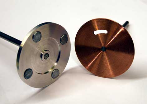
To determine whether I could make an Eddy Current coupling that would generate enough force to move a magnet against a spring force and what exactly it should look like, I performed a very extensive series of experiments. For this I made an aluminum disk in which I could press in neodymium magnets on various diameters and also a red copper disk in which the Eddy Currents are generated. I placed the aluminum disk with the magnets in the drill head of my milling machine and the copper Eddy Current disk in line underneath on a rotating axle. I sprung the Eddy Current disk with a tension spring so that it could only make a certain stroke. In this way I could vary a number of relevant parameters and deduce the influence of this from the angular rotation that the Eddy Current disk made with the same tension spring each time. I will not show all the measured values here, but I will give my most important conclusions:
1. The material of the Eddy Current disk.
The Eddy Currents in the disk will be larger as the electrical conductivity of the material is lower and thus also the torsional force. This also matched my observations: the generated torsional force was 2 to 8 times larger with a red copper disk than with an aluminium disk, depending on the distance of the magnets to the disk. In the tests, this distance was varied between 0.5 mm and 2 mm.
2. The distance of the magnets to the eddy current disk.
The large difference between red copper and aluminium was remarkable: for every 0.1 mm increase in distance, the torsional force decreased by approximately 6% with the copper disk, while it was approximately 20% with the aluminium disk.
3. The number of magnets.
With 3 magnets in the aluminium disk, the torsional force was approximately 40% larger than with 2 magnets and with 4 magnets it was approximately 60% larger.
4. The circumscribed circle of the magnets.
The circumscribed circle with which the magnets were in the aluminium disk also appeared to have a large influence, which is logical because with a larger diameter the circumferential speed is also greater at the same angular speed. On a circumscribed circle of 44m the torsional force was approximately 3.5 times greater than on a circumscribed circle of 22mm. The circumscribed circles were chosen relatively randomly with these experiments.
5. The circumferential speed of the magnets.
The influence of this was linear and was approximately 1.5x greater for a circumscribed circle of 44mm than for a circle diameter of 22mm.All this together has led to the choice of four magnets in the driven aluminium disc on a diameter of 40mm and a copper Eddy Current disc. The optimum distance of the magnets to the copper disc should be determined on the motor itself. Two other forces will play a role there:
1. The pulling force that the steel ball in the valve and the magnet exert on each other
2. The pulling force of a tension spring in the opposite direction.
Incidentally, I eventually replaced that spring with a counterweight as I will argue later on here. The speed at which the disc with the four magnets rotates does not only depend on the motor speed but also on the place where the rubber wheel on the drive shaft engages the flywheel. The best place for this was also determined later from the tests with the engine itself.
The elaboration of the engine design.
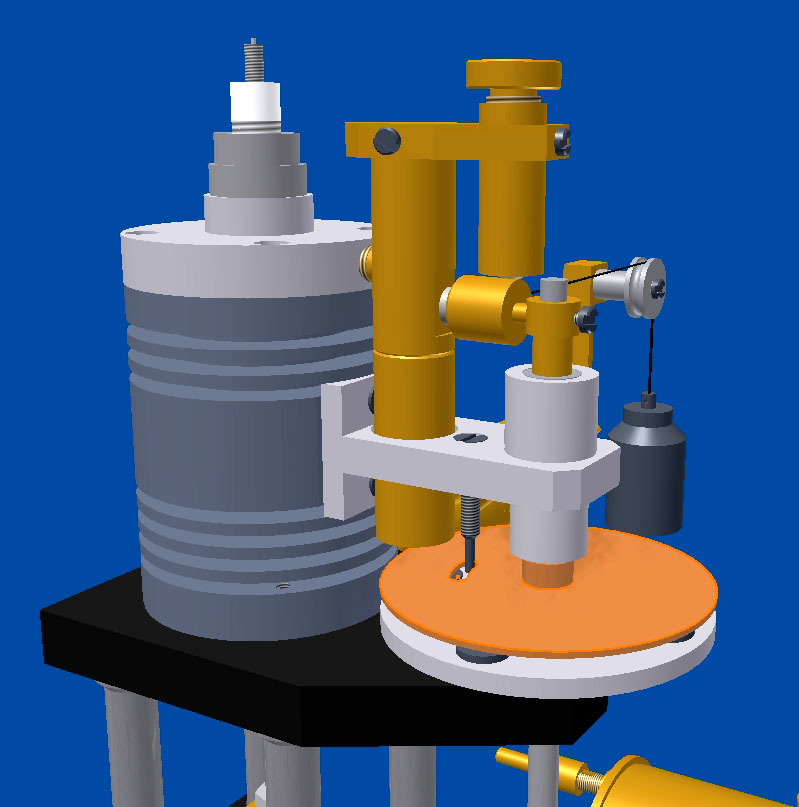
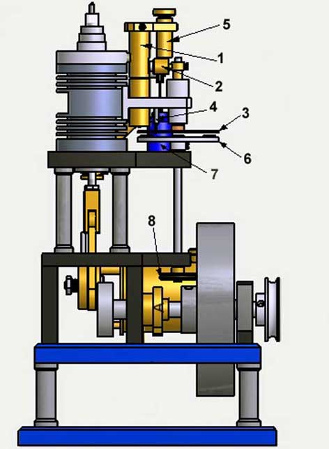
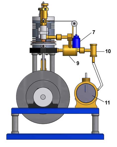
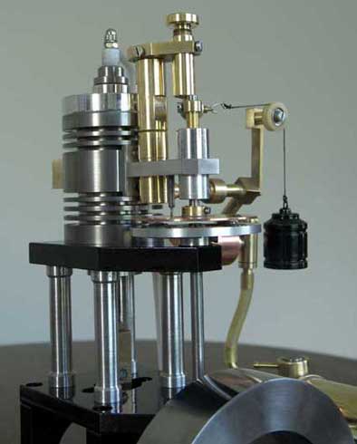
The numbered parts in the figures 1 and 2 below are explained further in the chapter Elaboration of the engine design.
Figure 1
Figure 2
Apart from the scaling up, I have therefore assumed the "Pressure-controlled 2-stroke engine" for the basic design. For the description of this, I can refer to the page of this engine. I will limit myself here to the constructions that cause the hit & miss behavior and some other details based on the above figures 1 and 2 and the various photos on the right of this page.
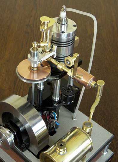
The system with the Eddy Current coupling.For constructional reasons I chose to have the magnet move in front of the side of the valve instead of above it. At the top of the valve there is an adjusting screw with which the stroke of the ball can be limited to approx. 0.5 mm. In addition, I later also made a construction on it with which the magnet makes a more "digital" movement; see the photo on the right of this page. These parts would therefore be in the way of the magnet. The magnet now pulls the ball slightly sideways from its seat, but that makes no functional difference. The ball valve is mounted as close as possible to the cylinder head in order to make the dead space between the piston and the ball as small as possible. Furthermore, I used a larger ball with a diameter of 7 mm instead of 4.8 mm. The reason was that I suspected that a greater gas passage would be necessary here, but also because the considerably heavier 7 mm ball is better attracted by the magnet and will also show less tendency to float or bouncing. The ball valve must first be screwed into the loose cylinder head before attaching this assembly to the cylinder. This is because the valve protrudes through a hole in the aluminum holder for the bearing of the axle of the copper disk. This holder must therefore also first be screwed against the side of the cylinder. All screw connections of this ball valve must be made airtight, for example by smearing a little sanitary silicone sealant on them.
The swinging magnet in front of the ball valve.
The neodymium magnet with a diameter of 6mm and a length of 8mm is pressed (or glued) into a brass holder that is attached to the axle of the copper disc. An eyelet is made on the back of this holder to which the counterweight (7) is attached by means of a flexible but strong yarn thread that is wrapped around a wheel; see figure 2 above and the photo on the right of this page. The distance from the magnet to the housing of the ball valve in the extreme (miss) position is approximately 1mm.
The copper Eddy Current disc.
The thickness of this disc is 1mm but that is not critical. The disc has a short slot through which the locking pin (4) protrudes and which limits the angular rotation of the disc and thus that of the magnet. The magnet must be secured to the axle of the copper disc in such a way that it remains exactly in front of the ball valve in the extreme miss position. The distance from the copper disc to the 4 magnets in the aluminum disc (6) is approximately 2mm.The locking pin.
The locking pin is an M3 screw in the aluminium holder for the bearing of the copper disc. This pin is inserted into a short slot in the copper eddy current disc, which limits its stroke and thus also that of the magnet in front of the ball valve. The diameter at the bottom of the pin has been turned down to approximately 1.5 mm to prevent the pin from touching the sides of the 3 mm wide slot in the copper disc.
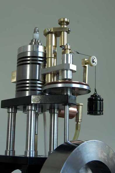
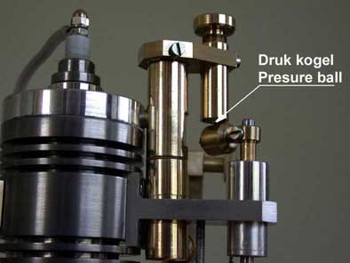
The tube with sprung ball.
This brass tube contains a steel ball that presses on the top of the magnet holder. An adjustable spring on top of the ball can be used to vary its pressure on the magnet holder. The effect is that the magnet makes a rocking movement under the ball, which causes it to remain in both extreme positions for a short while. Without this "digitalisation" of the magnet movement the engine actually only runs restlessly and there is hardly any of the typical hit & miss behaviour. If the ball in the valve is lifted even for a moment, the engine immediately goes into the miss phase and therefore runs slower, causing the magnet to immediately move away from the valve. Such an "analog" system then briefly oscillates cyclically around the point where the ball is lifted. Adding this "digital" mechanism turned out to make the most important contribution to the intended and characteristic hit&miss behavior of the engine.The aluminum disk with 4 magnets.
This disk must be made from non-magnetic material so as not to scatter the magnetic fields. I simply pressed the very hard neodymium magnets into it. The magnets have a diameter of 8mm and a length of 4mm, but with slightly different dimensions it will also work fine. The magnets have a north-south polarity and they must all be in the same direction, which direction is not important. You can check this by pointing a magnet in the same position against the other four. It must then always be repelled or attracted. The axle of this disk rotates in two ball bearings, one in the upper and one in the lower mounting plate. The speed of this disk depends not only on the engine speed, but also on the place where the rubber wheel (8) runs against the flywheel. Determining the best place for this wheel on the axle was a matter of "trial and error". Right at the top against the flywheel the speed is the highest but also the counteracting force that the engine then has to overcome and I got the impression that the engine had some trouble with that. In the end it turned out that the wheel could best be mounted at the bottom of the axle where it touches the flywheel on a circumscribed circle of about 45mm. The lowest speed but the system worked most stable with that.The counterweight.
When the engine slows down in the miss phase, the magnet must be pulled away from the ball valveagain. Initially, I used a light spring for this, but adjusting it turned out to be not very easy and/or unambiguous. The pulling force of the spring depends on the wire stiffness, the diameter, the number of windings, but also on its stretching. Finally, I replaced the spring with a counterweight that is connected to the magnet holder with a yarn thread; see figure 2. The yarn thread is wrapped around a wheel, which converts the vertical pulling force of the counterweight into a horizontal pulling force on the magnet holder; extremely simple and completely unambiguous. It remained to determine the optimum mass of the counterweight in combination with the various other forces in the opposite direction. It required quite a bit of experimenting to find the right balance, but in the end it worked out wonderfully with the various dimensions and settings as they are now shown in the drawing. The optimum mass of the counterweight turned out to be approximately 35 grams.The rubber drive wheel.
The rubber of this wheel (8 in figure 1) must be fairly soft so that it will continue to run well against the flywheel with light pressure, even if the flywheel shows a small wobble. Preferably use an O-ring that is as thick and soft as possible around the metal core of the wheel that is screwed onto the axle.
The fuel system
The carburetor; ïtem 11 in figure 2.
For this engine I have again and successfully applied the "Petrol vapour carburetor"; see the concerning page for the description and adjustment. It was with this engine that I discovered that the behaviour of this simple carburetor is considerably more stable if the pipe for the incoming air does not protrude into the fuel but remains approx. 10 mm above it, which is why I applied and/or changed this for all my engines.The expansion vessel (item 9 in figure 2).
In a 2-stroke engine, the fresh gas mixture from the carburetor is sucked into the bottom of the piston and is also compressed again when the piston moves downwards during the working stroke. The pressure of that compressed gas mixture may not become so high that it impedes the movement of the piston. The engine would not even run if that pressure at any time becomes equal to or higher than the ignition pressure above the piston. A normal 2-stroke engine has a crankcase that, in addition to housing the crankshaft, also has the function of limiting the pressure of the compressed fresh gas mixture. The dead volume in the crankcase is chosen in such a way that the gas pressure there remains substantially lower than the ignition pressure above the piston, but remains high enough to be injected into the cylinder through the inlet port above the piston at the right moment. This pressure contrlled hit&miss 2-stroke engine does not have a crankcase, which has greatly simplified the mechanical construction of this model. When the piston is in its lowest position, the space underneath is so small that the gas pressure would be many times too high. Of course, I could have extended the cylinder so that the dead volume under the piston would be so much larger that the correct gas pressure would be created, but then I would have had to make the length of the cylinder about 80% longer and I did not find that constructively attractive at all. It is much easier to include an expansion vessel in the pipe system outside the cylinder, as I also did with my
Pressure-controlled Two-stroke engine
Non-return ball valve (item10 in figure 2).
To prevent the freshly suc ked gas mixture from being driven back into the carburettor under the piston, a non-return valve must be fitted between the cylinder and the carburettor. For this I have again used a ball valve that regulates this automatically without any mechanical drive. As soon as the pressure above the steel ball rises, it is pressed onto its seat and if there is a vacuum during the intake, it comes loose again. To prevent the ball from floating and/or bouncing, especially at high speeds, the free play in the vertical direction must be limited to approx. 0.5 mm using a precisely made pin above the ball. With a floating or bouncing ball, it can happen that it does not fall back onto its seat in time, causing the engine to run irregularly or not at all. Opening and closing this ball valve correctly and on time is very important but no longer critical if the brass seat for the ball is turned nice and smooth and the free play of the ball is 0.5 mm with a tolerance of 0.2 mm.
The spark ignition.
It is my experience that 2-stroke engines need an energetic spark for reliable ignition of the gas mixture, which is usually less pure than with 4-stroke engines due to the less effective flushing process of the 2-stroke. Although there are several good circuits for a good spark, I still prefer the circuit with a coil as used in more classic cars or motorcycles. A bit large, but easy to work into the wooden base of this model so that this is not actually a problem. For the external DC voltage of 6 or 12 volts, I usually use the rechargeable battery of my hand drill machine that can be connected to the wooden base with a plug. Even more than with normal 2-stroke engines, it is very important with this hit & miss engine that the spark does not skip a single cycle. If it stays away for even a short while, this can be fatal, especially if this happens at the moment of restarting after the miss phase.
The flywheel.
The flywheel must be relatively heavy to keep the engine running well during the miss phase. With my simple construction with the half crankshaft, two flywheels cannot be mounted on either side of it, as is often seen with hit&miss engines. I turned the steel flywheel from the largest possible piece of steel that I could get my hands on. Although the engine runs well with it, I have the impression that it could have been a bit bigger/heavier. In any case, I do not think it is advisable to make the flywheel lighter than is currently shown in the drawing plan.
Starting and adjusting the engine.In good condition, the engine can be started by hand, but it is usually necessary or easier to do this with a loose belt around the pulley on the crankshaft and around a similar pulley in the drill head of the hand drilling machine. It is useful to block the magnet for the ball valve when starting this up, for example with a piece of rubber between the magnet and the ball valve. Because the engine then remains in the hit phase, it can first be properly adjusted. Once the engine is running nicely and regularly in this (normal) hit situation, this blockage can be removed and the engine will automatically "hit & miss" if the Eddy Current coupling is at least properly adjusted. When starting with fresh petrol, the control valve on the back of the carburettor must be set in such a way that very little gas mixture from the tank is mixed with relatively much air. Finding this setting point can take some searching and one often tends to turn the tap in the direction of more gas mixture if the engine does not want to start, which is absolutely wrong. This sensitivity has to do with a volatile component in the petrol that disappears quite quickly, which can be noticed by the decrease in engine speed. From that moment on, the regulator must be turned in the direction of a slightly richer gas mixture until the engine returns to the desired speed. Regulating the engine speed then also becomes a lot less sensitive. Like all my engines, this one also runs on normal car petrol to which I now add 1 to 2% thin (household) oil because I discovered that this contributes somewhat to the lubrication in the cylinder. A very good alternative for car petrol is Coleman Fuel. It is a super refined type of petrol that is used for camping stoves and can be purchased for 5 to 6 euros per litre at shops for camping supplies. Apart from the fact that it smells considerably less than car petrol, the main advantage is that it contains far fewer different hydrocarbons. As a result, there is little or no separation in the carburettor, making carburettor adjustment a lot less sensitive. The absence of heavy hydrocarbon components also ensures that virtually all of the fuel can be used.
Adjusting the system with the Eddy Current coupling.
The interplay of the various forces that make the magnet for the ball valve move back and forth is somewhat subtle. The pressure of the ball on top of the magnet holder that must ensure the "digital" skip (hit phase to miss phase and vice versa) is in fact the only thing that can still be adjusted with a running engine. All other parameters are in principle fixed settings such as the distance from the copper disk to the 4 magnets, the mass of the counterweight and the position of the rubber wheel against the flywheel. If everything is made and set according to my e drawings plans, the ideal hit & miss behavior should be able to be set by only varying the ball pressure on the magnet holder.
Finally:
- I have mounted a brass block on the exhaust hole of the cylinder on which an exhaust muffler can possibly be attached. I have not done that myself because I can now easily let a drop of oil fall through the hole to keep the walls of the cylinder and those of the piston in good condition. This light lubrication is only necessary occasionally, but it is advisable to do this if the engine is stored for a longer period of time. A muffler (silencer) on a 2-stroke is a special profession and can produce all kinds of unpredictable negative and positive results exept the passage is kept large. In that case, such a silencer will only have a cosmetic function, which can be quite nice of course.
- The sound that this 2-stroke hit&miss engine makes differs considerably from the sound that classic hit & miss 4-stroke engines usually make. One may find this a pity, but apart from the fact that the sound of a 2-stroke is naturally different from that of a 4-stroke, this is a unique and idiosyncratic design and so it is not surprising that it produces a unique and idiosyncratic sound. In any case, the thing is unmistakably "hit and miss" beautifully.Video:
Drawwing plan.
I madw a CAD drawing plan package for this Hit & Miss 2-stroke engine that is available for any-one interested, for a request click here.
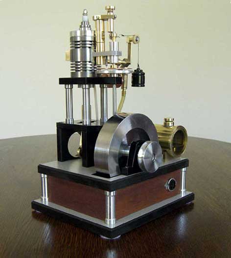
Nice replica made by Gerard Versluys: