Introduction
I always make my models only according to own designs so I never follow existing drawings or concepts. It's just my forever striving to make model engines with one or more unique features, but mainly based on existing principles, so not making spectacular inventions. It is actually more "playing" with the basic physics that presumably is a consequence of my working life as a process developer in the field of gas exchange, vacuum techniques and dosing systems. It is a kind of professional deformation of a developer trying to do everything different whether it is necessary or not.
Another feature is that my designs always must me as simple as possible from a mechanical point of view, if only because I cannot make the model myself due to my fairly limited mechanical skills and tools.
I never seek for practical use, high performances and/or efficiencies. That I leave on to industrial designers who possess the knowledge and experience, having the technical resources and who are being payed for it.
The disadvantage of my method is that it is increasingly difficult to again and again find new ideas and to convert them into a working model. This leads more and more to rather bizarre models which I myself find kind of funny, but others probably will look at it with some amazement.
This project is a typical example of such a weird venture. A 2-stroke engine with only one piston in a glass cylinder in which the process takes place alternately on both sides of the piston that is fixed on one common axis.
Concept 1: Free running piston
As the piston is pushed away by the cyclical gas expansion of the gas combustion (be it left or be it right) it will cause compression of the fresh gas mix on the other side of the piston at the same time. It's like an engine with a free running piston from what there are several concepts, although I do not know how they are constructed exactly. I could not find much industrial applications so I assume the success of it is not that big.
If this concept should work it is again not more than a kind joke without some practical value, although it is for example conceivable to drive a pump with it or a small generator with a moving magnet in a coil to make some electricity. But as I said this is never my intention, so it will probably remain only a unique model with what the combustion fires will be visible again through the glass cylinder on both sides of the piston. It's just what you like.
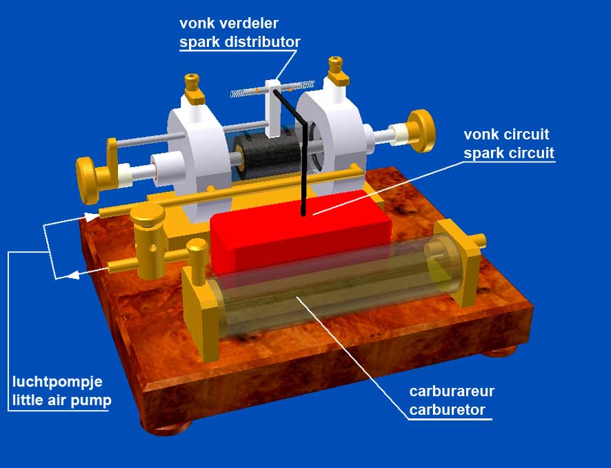
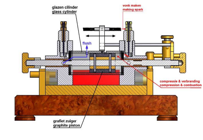
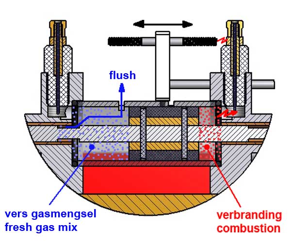
The CAD pictures below illustrate the design of this concept 1:
Figure 1
Figure 2
Figure 3
The gas exchange process
I opted for the 2-stroke process because I think this is actually not possible with a 4-stroke process here because that process is over 3/4 of the time labour free. This also apart from the fact that a 4-stroke construction would be much more complex as a result of a required double valve system with a 1 to 2 distribution.
The glass cylinder has two ingrained outlet ports through which the exhaust gases escape, and which make it possible to flush the space under the piston again with fresh gas mixture from the carburettor; see figure 3. The piston axle has two constrictions that serve as gate valves. At the right moment the one or the other side of the cylinder is alternately flushed with the fresh gas mixture from the carburettor which is then compressed and ignited when te piston moves back in the opposite direction.
The problem is that the piston itself can not suck this fresh gas here because the process is always on the same side of the piston so the gas combustion and the intake can not occur simultaneously of course. For this preliminary design, I have put a little aquarium air pump between the carburetor and the inlet of the cylinder that makes a constant low pressure fresh gas mixture from the carburettor but with sufficient flow; see figure 1. I already have tested this on two of my 2-stroke engines and it works fine by itself. If everything works properly, it is in principle always possible to make a little pump mechanically driven by the engine itself. This is possibly a continuation of the project, but I will first look at how everything turns out with the aquarium air pump.
The spark ignition
I had to to think of something special because here because the one and then the other spark plug must get alternating the high voltage at the right moments, so I had to make a kind of spark distribution. I made the following solution which actually appears to be very simple:
I used the circuit of the "Blokker" gas lighter again that I will not change at all in this case. It will be constantly connected to the 1.5 volt supply battery as normally is the case using it as a gas lighter. The flexible high tension cable is connected to the spark distributor as shown in figures 1 and 2. This spark distributor is mechanically coupled to the piston shaft and thus moves together with the piston from left to right. The little springs at the ends thereof touches each time one of the spark plugs at the moment the spark must occur there. The contacts on the spark plugs can be slightly rotated so that the timing of the sparks can be adjusted accurately. The spark will automatically extinguish if the distributor is more then about 6 mm away again from the spark plug and this is well before the piston reaches the exhaust port so the fresh gas mixture cannot not be ignited when it flows through the cylinder through the exhaust port. In this way the need for two micro-switches or reed switches with the constructions to drive them can be omitted.
The engine behaviour
In fact the gas ignition on the one side of the piston provides the compression on the other side of the piston and vice versa. According to the design the stroke of the piston is restricted by rubber pads on the outside of the piston axis. The limitation of the stoke will also be partly determined by the compression generated by the piston movement. Also the timing of the spark will have an impact because the piston will reverse at the moment the gas mixture is ignited.
All in all it was difficult to predict what the speed of movement of the piston would be, not in the least because there is hardly a load in the form of significant mass inertia or pressure springs in this design.
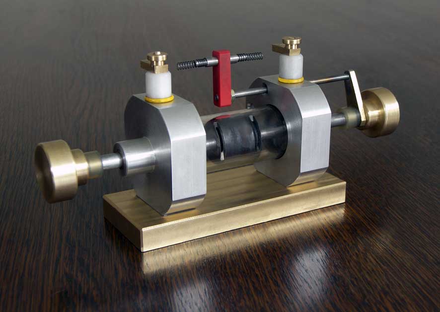
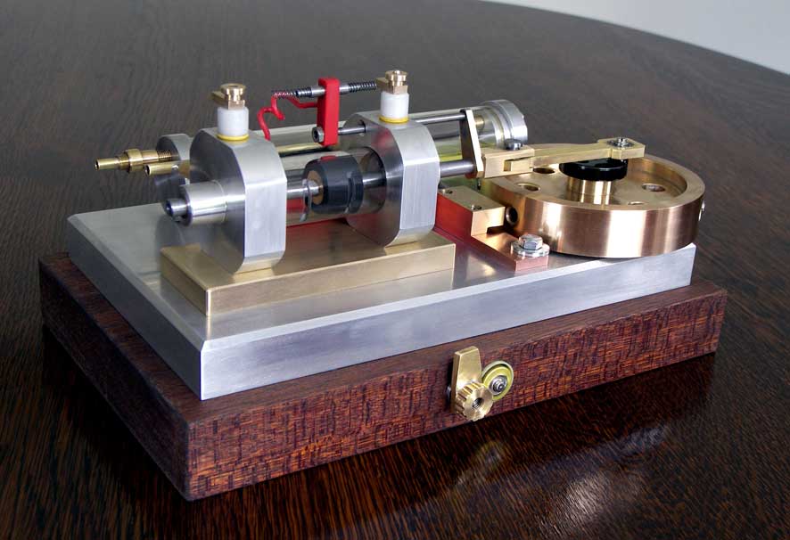
The main part of the engine is shown on the picture below:
I made a test set-up, fixing this part of the engine with the brass base plate in a loose machine vice and connected the carburettor via the small aquarium well pump and also the "Blokker" circuit on the spark distributor. When I manually pushed or drew the piston axis to the left or to the right the bright blue gas explosions immediately occurred on either side of the piston. So, in principle everything worked well as I expected. But also something else happened: at the moment one of the exhaust ports is opened the expansion pressure vanishes straight away so that the piston is pressed insufficiently far to make the needed compression on the other side of the piston. To solve this problem, I increased the mass of the piston shaft with pretty heavy weights instead of brass buttons as you still can be seen in the picture above. I also reduced the length of the piston with few steps to give the piston axis some more time to accelerate due to the inertia of the weights. In this way the piston-shaft combination is moving like a bullet shot from a gun barrel but alternately in opposite directions in this case. At one time the engine made a few turns and then I was scared to see the extreme violent behaviour: the whole system including the quite heavy vice trembled just complete from the workbench; exciting to see, but not exactly the intention of course !!After a lot of experiments I unfortunately had to conclude that this concept has no chance for success for the following reasons:
1. The expansion pressure on the piston which also has to provide the compression on the other side of it is cut off instantly when the piston opens the exhaust port. In order to enable the piston to make sufficient speed, quite a large load must be added to the piston axis.
2. The piston/mass combination is alternately and in opposite directions catapulted, causing an unacceptable rumbustious motor behaviour.
3. If there is only one ignition failure the engine will stop running immediately and irreversibly because there is no element that helps the engine to overcome such a dead moment in the process.
In short: here the effect of a flywheel is lacking with what the stroke of the piston is mechanically forced and that helps the engine to survive a dead time in the process.
I should have known this, but I was seduced and deceived by the success of "Bounce 2-stroke" which also has no flywheel. But this engine makes a single-stroke without building up any significant pressure to the other side of the piston, wherein the force of gravity acts on the weight hanging on the piston which is not the case here.
I already intended to put the thing in the gallery "failures" but I changed my mind. Why not still apply a flywheel and maintaining the other elements of this design?
Concept 2: The "Dual 2-stroke"So I added a flywheel to the design, leaving the rest of the free piston concept virtually untouched. Because the piston is no longer running free I renamed the engine "Dual 2-stroke" to indicate that the two-stroke process is (still) playing on both sides of the same piston.
The pictures below show the construction of this changed concept:
There was a problem with the spark system: with the free-running "Blokker" circuit the sparks already occurred 4 to 5 mm before the springs touch the contacts on the spark plugs. The sparks are thus slightly too early which sometimes caused back strokes. This can not be avoided in this way because it is not possible to let the spark only come exactly on the extreme positions of the piston or preferably even a little later but never before. I had actually did expect this phenomenon but I was hoping that the ignition delay would solve this problem automatically, but this time the luck was not with the stupid.
I also had the impression that the energy of the unaligned Blokker circuit actually is just too low to ignite the gas mixture always reliable.
I have therefore again applied the modified Blokker circuit that is triggered by a reed switch that is switched by two magnets in the flywheel. This modified circuit also has the advantage that the spark energy is a lot higher due to the larger capacitor and the the higher voltage thereon as an effect of the removal of the zener diode.
The engine now runs nicely with a speed of 600 to 1000 rpm as you can see on the video below:Video:
Possible follow-up
The gas mixture from the carburettor with some low excess pressure is still provided by means of a small aquarium air pump. It works nice, but it's actually somewhat improper and forced. It would be nicer to add a pump to the design on the other side of the flywheel that is mechanically driven by the piston axle. Not that easy to make such a little pump with sufficient yield but I might attempt to do that anyway sometime.
VNo drawing plans for the time being
Only if I find an accetable solution for the gas mix pump problem I will make the drawing plan available again to avoid appointments.
