A 2-cylinder 4-stroke engine with intake ball valves
and a lateral cam disc for the exhaust valves
Introduction
Early 2009 I made a 4-stroke engine with what I substituded the classic system for intake and exhaust valves with all driving mechanisms for it (like pop valves with seats, tumblers, valve pushers and cam discs) by only one single rotary disc valve; see the concerning page. This rotary valve is not integrated in the cylinder head as you mostly or always see in other designs for rotary valves. Here this valve is mechanically and thermal separated from the cylinder with the advantages I described in the page mentioned above.
This disc valve engine is running perfectly, but already at the end of that project I had the feeling that it still could have been made easier, not regarding the process but the mechanical set-up. The rotary part of the valve is turning against the stationary part so I needed a spring system that presses both disc valves to each other to realize a continuous and air tight contact. That appeared to be less easy than I assumed before and I had to implement a double spring arrangement to finally obtain a good sealing. As said a very nice running engine but with a somewhat forced and unsatisfactory spring mechanism.
introduction
So I now have designed and made a 2-cylinder engine with automatic intake ball valves and a simple lateral cam disc that serves both exhaust valves.
The design
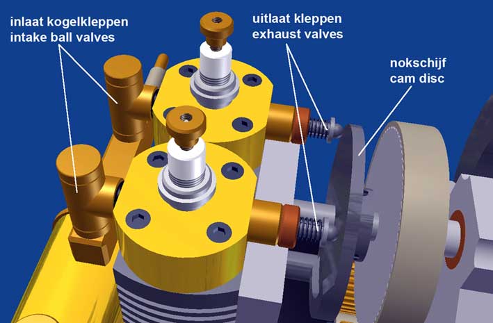
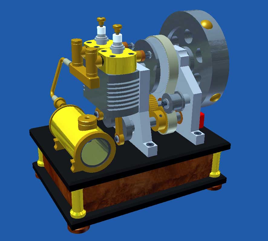
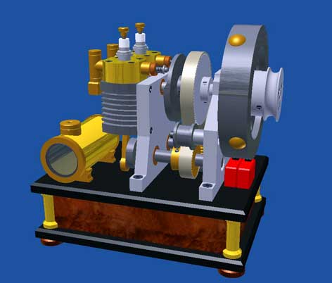
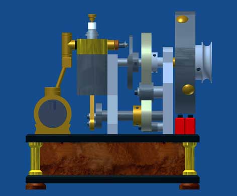
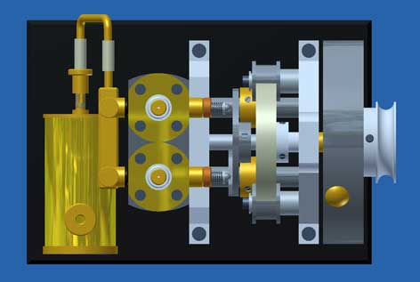
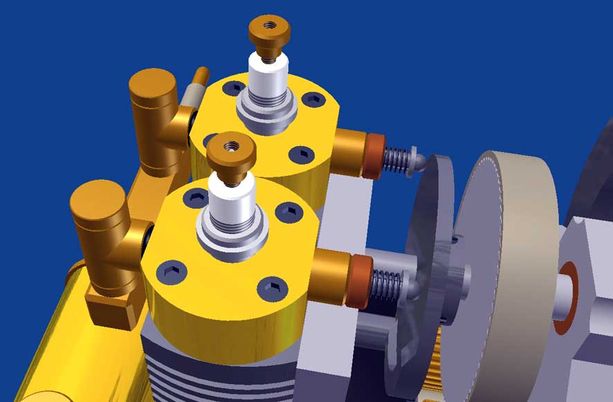
The CAD figuers below illustrate this design:
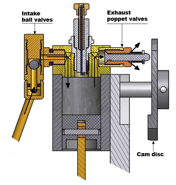
The two pistons of pearlitic cast iron (GG25) are running in a cylinder block which is made of the same material. The two separate brass cylinder heads are connected to the carburetor with two parallel ball valves for self sucking the fresh gas mix from the "Petrol Vapor Carburetor." For the exhaust I pressed bronze bushes with valve seats in the cylinder heads in what the the spring loaded exhaust valves are gliding. In the steal valve stems three slots are machined at an angle of 120 degrees through which the exhaust gases can escape as the valves are opened by a rotating disc with a lateral cam profile. A valve stroke of only 0.5 to 1 mm appears to be sufficient for complete exhaust of the burned gases.
Both valves are in the same circle as the cam disc with the same lateral cam so they are pushed open with the same cam. Since the pistons are shifted 90 degrees in phase, the cam exactly pushes the second valve 90 degrees later than the first one. This can only be done when half the distance between the valves is equal to the distance between the plane through the valves and the center line of the axle through the cam disc.
To create the sparks, I just made two separate circuits with relatively small motorcycle ignition coils that I could install in the wooden base of the engine. They are controlled by two separate cams at 90 degrees on the flywheel. I have not chosen for a high voltage spark distributor because that is very difficult to make.The gears for the timing belt
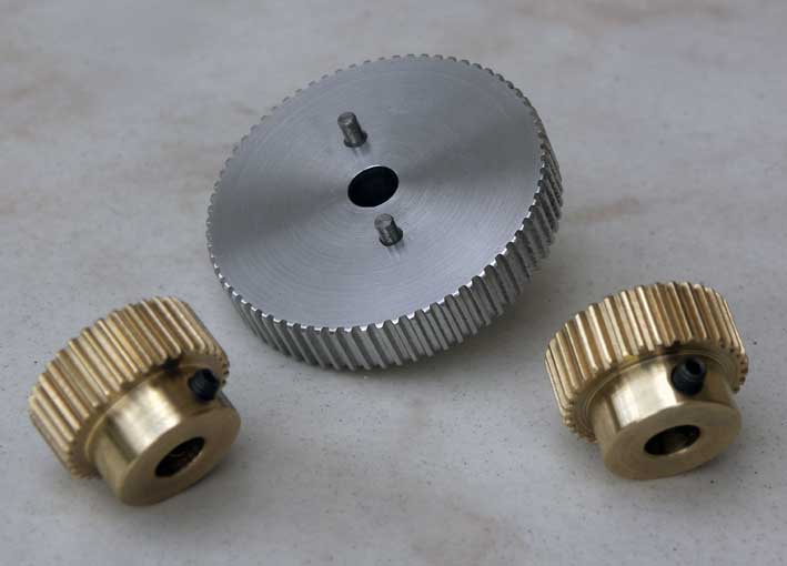
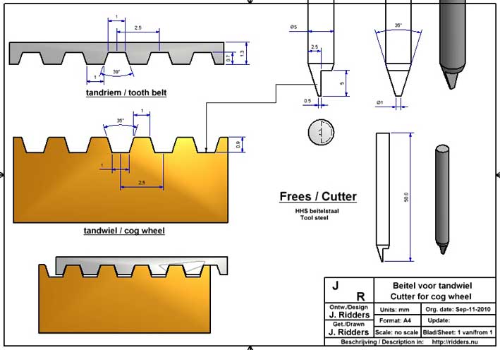
I have made the gears for the toothed belt myself because it is not easy to get them , and also because they are quite expensive, you pay for this set of wheels about 70 Euro plus shipping. They can very well be made by yourself at least if you have the disposition of a distribution disc under the mill. The teeth of this type of belt wheels are just trapezoid and so much simpler than that of gears that run together and for what you need special module cutters. I used a simple homemade cutter with two cutting edges made of a hard steel punch nipple. I have first studied the dimensions of the timing belt and gears and generate the correct angle for such a cutter, see the CAD drawing below that I made for this:
The diameter over the teeth depends on the number of teeth you must make and the pitch which is 2.5 mm in this case. Making the exact diameter of the toothless wheel is very important and I could get these data from manufacturing sheets. It is of great importance that this diameter is made precisely in order to ensure that the belt will run nicely over the wheels.
Making these gears is a quite a job but I succeeded to do that wonderfully with these simple tools, see the picture below:
The result
In fact this engine is a very simple 2-cylinder 4-stroke engine, mainly because here twice two valves in the cylinder heads are missing, including the drive systems therefor with 1 to 2 distribution, four cams, four tappets and four tumblers. The engine runs on ordinary auto car gasoline car in the Petrol Vapor Carburetor and can easily be started eg with a hand drill on the pulley against the flywheel. The motor speed can be adjusted with the controller on the carburetor between approximately 600 and 1500 rpm.
As with all my little engines little here again the difficult issues are lacking such as grinding and casting, forced cooling and lubrication systems, oil sump, complex crankshaft, etc. The whole thing can be made with only standard lathing and milling from standard materials so that each "average" modeler (like me) can make it if he sees the fun of it. It also has its limitations; you should not try it out for hours to pull a cow out of a ditch.
Replica made by Monty Lenard: