General
The Scottish clergyman Robert Stirling (1790-1878) invented this type of engine, reason why they are named after him. On the Internet many descriptions can be found, more or less profound.
My description on this page concerns only the most elementary principle on which all my models are based.
The global motor construction
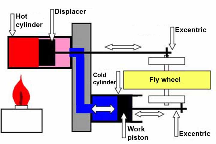
A Stirling engine always have a hot cylinder in which the so-called "displacer" is moving and a cold cylinder containing the working piston. The engine construction is always in such a way that these two cylinders are connected atmospherically with each other and together enclose a fixed air volume. The connecting rods of the displacer and that of the working piston are each connected to their own eccentrics which, together with a flywheel, are mounted on a light running axis. The eccentrics are always 90º shifted relative to each other. This can of course be done in two ways, which is decisive for the direction of rotation of the engine.
For the heating of the hot cylinder usually a spirits flame applied, but any other choice is good as long as sufficient heat is supplied.
The diameter of the displacer is less than the internal diameter of the hot cylinder and that in the order of 1 to 2 mm. When the displacer is running going back and forth the air in the system is moving along this gap periodically from the hot zone in the hot cylinder to the relatively cold zone where the cold cylinder is situated containing the working piston. Thus, the air is alternately heated and cooled expanding and contracting by that. This causes an alternating force to the working piston which delivers the power of the Stirling engine. The working piston must fit well into the working cylinder, but in such a way that it can move therein with minimal friction. The flywheel assists the movement through the dead points, so that the process cycle will be repeated as long as heat is supplied.
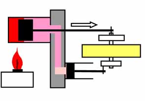
To the right of this page the process is explained in more detail by means of four positions of the displacer and the working piston in the 360-degree cycle.
Engine performance
The air pressures in the system are only a part of an absolute atmosphere so the engine power therefore is relatively low. So it is important that the rotating elements run very lightly with low frictions whereby the use of (grease-free) ball bearings for the rapidly rotating parts is preferable other than slide bearings. Everything must be aligned well to reduce torsion and frictions to a minimum.
In doing so speeds up to about 1000 revolutions per minute can be realized. Depending on the size of the motor and the applied de-acceleration a small device can be driven eventually.
Adjustments
The adjustments and applied materials can be critical with this kind of "fleed-footed" Stirling models.
See the page "Experiences & Tips" for this Stirling model engines.
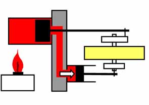
The air in the hot cylinder is heated in the section left of the displacer and expands.
The air can freely expand along the gap between displacer and hot cylinder, whereby a force to the right is exerted on the working piston.
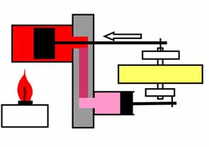
The hot air is displaced along the gap between the displacer and cylinder to relatively colder (right) part of the warm cylinder. The air starts to cool down in the right part so that the pressure starts decreasing.
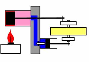
The air to the right of the displacer and in the working cylinder is cooled down to maximum causing negative (under)pressure. The outside atmospheric pressure now applies a force to the left of the working piston.
The cooled air is pushed back into the hot left-hand portion of the hot cylinder and warmed-up again. The process cycle repeats itself while the fly wheel helps the movement over the two dead points.