The idea
Surfing on Internet for articles about Stirlings I found a fairly vague photograph of a small device that, according to the accompanying text, was used on schools to explain the stirling-principle. It showed a glass test tube with glass balls in it. This tube was connected with a rubber hose to something that looked like a cylinder with a piston in it, but there was no further explanation. The looks of the model was, with respect, very "elementarily". Because I already had build several Stirlings I thought to understand how it worked or could work. Judging by that faith, I start designing and building an engine that, at the end, proved to be a very unique and nice Stirling engine. It is very close to the basics of the stirling principle which you can see very well.
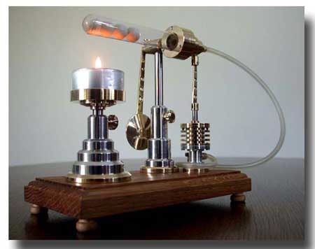
With this design there is kind of swinging movement other than a normal rotation of a flywheel. Because of its somewhat unstable but cute behaviour I gave this engine the name "Stirling Onrust", free translated "Stirling Restless".
Video:
The working principle
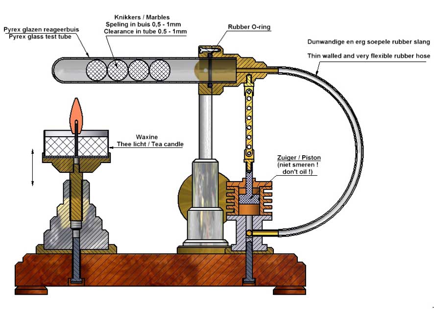
A glass test tube is connected to a brass clamping piece by means of a rubber O-ring, so that this tube is both mechanically as well as airtight fixed in it. A small axis square on this clamp piece can turn in a glide bearing. So the clamping piece with test tube can swing up and down in the vertical area.
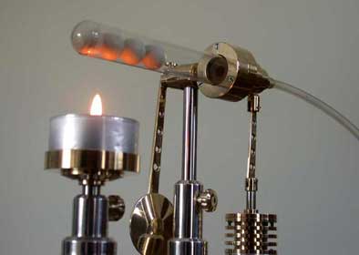
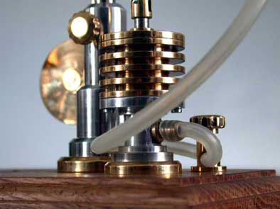
Four ceramic balls in the tube roll from left to right and vice versa, as result of the swinging movement of the tube. A small bore in the clamping piece prevents the balls rolling out of the tube. This bore ends in a hose socket. The thin and flexible hose on it is with the other end connected to a metal cylinder in which a piston can move up and downwards.
On its turn the piston rod is connected to the clamping piece, so that the testtube is swinging as the piston goes up and down.
A little flame of a candle or a spirits burner heats the closed end of the glass test tube. As a result the air in it expands pushing up the piston. By that the tube swings down and the balls roll to the closed end of the tube. As a result of that the heated air is pushed between the balls and the inner wall of the tube to the cold area where the tube is fixed to the clamping piece. The air is cooling down there as a result of which an under pressure occurs which make the piston to move down again. As a consequence also the piston is continuous moving up and down swinging the tube with the rolling balls in it. And so the working cycle is closed.
The system is also working according to the very basic Stirling principle.
Adjustment of the "Stirling Restless"
Adjustment of this instrument took me a lot of time at the beginning, until I discovered that I had to add a kind of a clock pendulum to the system. This pendulum causes a certain time constant to the system and makes it possible to adjust its equilibrium. The pendulum is fixed wit a screw to the axis of the clamping piece which make it possible to re-adjust it. This appeared to be necessary because after some time the amount of air in the tube reduces somewhat due to the overpressure. Some air escapes along the piston which is, of course, not absolute airtight. Because of that after some minutes a new equilibrium is set through which the balls could stick to one end of the tube if one shouldn't intervene. The original equilibrium can be repaired by readjusting the pendulum on the axis and fix it again. From that moment the engine proper keeps moving at which the balls roll "as a little train" aginst each other.
A cute little instrument that swings as long the flame of the candle is there, with a tempo of about 1 swing per second.
The heat resistant glass tube
This kind of heat resistant (pyrex) “Duran” test tubes are rather standard and common although you cannot buy them on every corner of the street. You can find suppliers for this kind of good quality glass tubes on internet also (try “Duran or Schott Fiolax test tubes” on Google Search), although they mostly sell only rather big packing quantities. But if you contact them they sometimes are willing to send you some free samples if you tell them that you need them for a model engine. I know some model builders succeeded in doing so. The diameters can differ somewhat from the drawing plan but that is no problem as long as you adapt the dimensions of the related parts conform.
Some suppliers for these kind of heat resistant test tubes:
click here or here or here
Ceramic balls
Originally I used ceramic balls which are ideal for this purpose because they are light in weight and therefore do not break the head of the glass tube when they hit it. I once managed to get hold of a few from my former employer where they were used to grind powders in a drum.
However, as far as I can tell, these ceramic balls are no longer for sale anywhere. It also works well with toy marbles, but they usually squeal from thermal stress so that they easily break when they are heated. Sometimes it seems to work if they are properly made tension-free. They do seem to exist, but of course it is not visible from the outside.
I later found out that it also works well with steel balls with a diameter of about 13 mm and they can be found everywhere on the internet. Because the speed at which the balls roll back and forth in the glass tube is low, they usually do not break the head of it either.
Drawing plans
I made a CAD drawing plan for this Stirling that is available for every one interested; click here for a request.Variants
I made two variants of this Stirling with ceramic balls:
1. "Onrust Maarten"; almost the same engine that I made for my sun in law Maarten as a birthday present.
2. "Ja Knikker"; a flywheel type with complete different behavior.