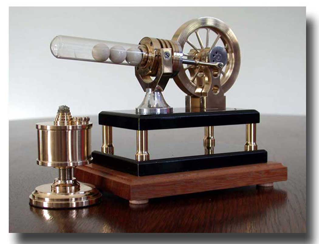
The classic construction of a Stirling engine
The air in a Stirling engine is cyclically displaced in a closed volume from a hot to a cold zone. As a result this air expands and shrinks also cyclically, providing the alternating force on the working piston; see the page about the Working principle of a Stirling engine.
In the classic construction the air displacer is a piston that moves in a so called "hot cylinder" with some space, so that the air can pass between this displacer and the internal cylinder wall. The displacer and the working piston are both connected to a crankshaft with a flywheel on it.This alternative Stirling design.
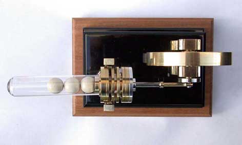
In this design the displacing of the air is realized in a complete different way. Three ceramic solid balls can roll in a glass test tube that is heated at the closed end of it with a spirits burner. This rolling balls displace the air in the tube from the hot zone to the cold zone and vice versa.
I found this "ball concept" on an internet website, where it was implemented in a test tube Stirling, mend for education purposes. The test tube with solid glass balls in it was connected to a separate cylinder with the working piston by means of a flexible rubber tube.
Earlier I build two somewhat more sophisticated versions of this concept which I named "Stirling Onrust"; see the models "Stirling Onrust Jan" and "Stirling Onrust Maarten". "Onrust" is Dutch for"restless" and this is more or less the character of these models. Nice Stirlings if you ask me, but a little bit unstable, despite the implementation of a pendulum as a stabilization element.
To realize a more controlled running variant I presumed that I had to eliminate the rubber tube and implement a flywheel in stead of a pendulum. The only question was if a flywheel could keep an implicit equilibrium in score in this moving system because a flywheel is a constant and a not re-adjustable element. But it appears that the luck was with the fool again.
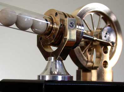
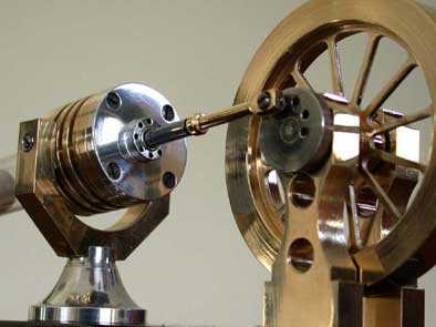
In this new and very unique design the working cylinder with piston is directly and gastight connected to the open cold end of the glass tube. This assembly of glass tube (as "hot cylinder") and the cylinder with the working piston can swing in the vertical plane around a horizontal axis. The push rod of the working piston is connected to a singular crankshaft with the flywheel on it. I use ceramic solid balls because almost all glass balls easily burst when they are heated.
This construction fulfil implicitly the demanding condition for each Stirling that the ball displacer and the working piston are under 90º in the moving diagram.
The motion of this engine is very serene with a constant low tempo of about 40 strokes per minute. It does think of an oil pump in the field which is called a "Ja Knikker" in Dutch; free translated: a "yes-nodder". And this is the reason why I gave this Stirling this name.
The flywheel doesn't run in the usual way with a relative high and constant revolution speed. It is curious to see how the flywheel is pushed two times in the cycle, due to the expanding and the shrinking of the air in the system and how it helps the motion to get over the two dead points in the cycle. In my opinion this model is one of the most "basic" and transparent designs of a Stirling engine.Video:
A remarkable teamwork of divergent phenomena !
For those who want to see it here an almost perfect teamwork between a number of different mechanical and physical phenomena executes itself:
1. The crankshaft not only transposes the alternating piston motion into a rotating motion of the flywheel, but it also causes the swinging of the assembly glass tube/working cylinder. This in combination with the special attachment of the cylinder in a fork;
2. It is the gravitation force that causes the ceramic balls rolling from left to right and vice versa;
3. The rolling balls pushes the air in the glass tube from the hot to the cold zone and reverse;
4. Due to this displacement the captured air expands and shrinks by which the working piston encounters a force two times in the cycle that reverses on the right moment in that cycle;
5. The flywheel helps the motion to get over the two dead points in the cycle, so that that the motion is repeating as long as the spirits burner supplies energy to the system;
6. Is is mainly the mass-inertness of the balls that determines the very serene and constant tempo of the oscillating motion of the engine.A physically orientated spectator may say that this is all obvious. But in my modest opinion it is very wondrous that this harmonious teamwork between so divergent phenomena takes place in such an uncomplicated engine design !
The heat resistant glass tube
This kind of heat resistant (pyrex) “Duran” test tubes are rather standard and common although you cannot buy them on every corner of the street. You can find suppliers for this kind of good quality glass tubes on internet also (try “Duran or Schott Fiolax test tubes” on Google Search), although they mostly sell only rather big packing quantities. But if you contact them they sometimes are willing to send you some free samples if you tell them that you need them for a model engine. I know some model builders succeeded in doing so. The diameters can differ somewhat from the drawing plan but that is no problem as long as you adapt the dimensions of the related parts conform.
Some suppliers for these kind of heat resistant test tubes:
click here or here or here
Ceramic balls
Originally I used ceramic balls which are ideal for this purpose because they are light in weight and therefore do not break the head of the glass tube when they hit it. I once managed to get hold of a few from my former employer where they were used to grind powders in a drum.
However, as far as I can tell, these ceramic balls are no longer for sale anywhere. It also works well with toy marbles, but they usually squeal from thermal stress so that they easily break when they are heated. Sometimes it seems to work if they are properly made tension-free. They do seem to exist, but of course it is not visible from the outside.
I later found out that it also works well with steel balls with a diameter of about 13 mm and they can be found everywhere on the internet. Because the speed at which the balls roll back and forth in the glass tube is low, they usually do not break the head of it either.
Some specifications
Outlines l*w*h= 170*100*120mm;
Diameter working piston= 11mm, the stroke= 11mm;
Diameter glass test tube= outer 16mm, inner 14mm, the length= 75mm;
Diameter ceramic balls= about 13mm;
Diameter brass flywheel= 65mm, width= 10mm.
Drawing plans
For this Stirling I made a CAD drawing plan that is available for every one interested; click here for a request.
Nice replica by Pieter de Jong:
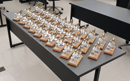
40 nice replicas made by
students of
Steve Johnson:
Nice replica made by
Ben Trueblood: