The Idea
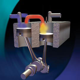
Surfing on Internet a colleague modeler found a recent patent (2003) of a new type four-stroke internal combustion engine. The four strokes are split over two cylinders with coupled pistons. One piston sucks-in the fuel mix (intake) and compresses it in a volume between the two cylinders. In the other cylinder the compressed mix is ignited (power stroke) and the burned gasses are driven out (exhaust); see the picture below.
Scuderi principle
The typical characteristics of the Scuderi engine
The three most remarkable differences with the classic 4-stroke engines are:
1. With every fly wheel revolution there is a power stroke because the intake and compression of the fresh gas mix in the one cylinder happens simultaneously with the combustion and exhaust in the other cylinder. To this respect the behavior of this 4-stroke engine is the same as a 2-stroke engine where these processes occur on both sides of a single piston.
As a result of the 1:2 distribution between the crank shaft and the cam shaft as is usual for the classic 4-stroke engine is absent with this split cylinder Scuderi engine.
2. The compressed gas mix is ignited when the piston in the power cylinder is already 40° away from its highest position (TDP). According to the Scuderi patent this is the most important reason for the better efficiency because at that ignition moment the crank shaft is in its optimum drive torque position.
3. The intake/compression piston is shifted 40 ° back form the combustion/exhaust piston.With this Scuderi design it is possible to make different diameters and/or strokes for the separate pistons. The possible effects and advantages are given in the Scuderi patent, but for me there was no good reason to do this for my model engine.
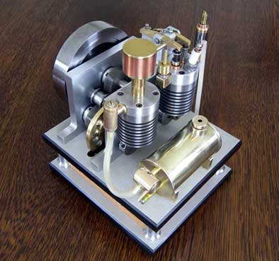
The global design and work-out
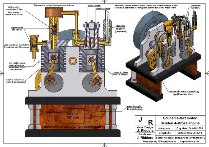
Below Sheet 2 of the recent CAD drawing plan (May 2010) for orientation.
Left cylinder: Intake of fuel mix from the petrol foam carburetor & compression in the in between volume.
Right cylinder: Ignition (power stroke) & exhaust.
1. The design lay-out.
Other than the picture above and the animation shown in the Scuderi website I choose to separate the two cylinders completely from each other. The main reason for that is that the construction of the model becomes much more easy, which is always my personal strive. The piston rods can be easily mounted on the crankshafts with ball bearings. Additionally the center lines of the pistons and the crankshafts are in line, which is beneficial for the interplay of forces and it results in more space for the piston rods in the cylinders. This in contradiction to a combined crankshaft in the middle of the two cylinders which is much more complex to make and with what split-up shell bearings must be applied.
Making two separated cylinder heads with the compression volume in between is also more easy than combining everything in one head on one cylinder housing.
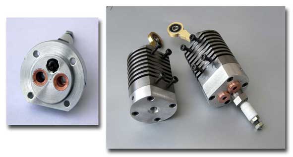
2. The cylinders and pistons.
Just as with all my other IC engines I eliminated crank cases in what normally the crank shaft is rotating in an oil bath. This makes the construction significantly more easy. With the use of pearlitic grey cast iron for the cylinders and the pistons as well it is sufficient to dose a single oil droplet from time to time in the cylinder to "keep the surfaces in good condition" and to avoid any rust when the engine is stored for a longer time. The thermal expansion of pearlitic grey cast iron is very low and the same for the cylinder and piston. this material is very wear free and it is more or less self greasing due to the high carbon content. All reasons why I never have troubles with jamming pistons without a forced greasing and cooling system. Mind that a run time of about 10 minutes is more than enough for a successful demonstration of the mode. Furthermore the engine speed of 500 to 1500 rpm is low compared to industrial engines which are made for heavy duty tasks.
This cast iron also allows me also from skipping piston rings with the big advantage of very low frictions. It is rather easy to make very smooth cylinder bores with small piston clearance of about 0,005mm. For that I reamed the cylinder bore manually with an adjustable reamer turning the cylinder around and around several times with the same reamer adjustment, adding ample oil. Then adjusting the reamer a fraction wider and repeat this treatment until I could not measure any diameter difference anymore. to make the cylinder bore exactly cylindrical. This way of working can compete with honing for what I don't have the equipment. Then I made the piston diameters a fraction oversized and grind them in the cylinder bores with very fine grinding paste until they move in the cylinder as "driven by the wind".
The temperature of the compression cylinder remains almost at room temperature and the power cylinder don't exceed a 110 á 120°C temperature at stabilization. This allows me to eliminate forced cooling and greasing system and it will be clear that this makes the design extremely simple.
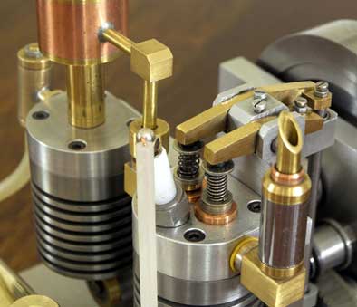
It is always of big importance that the valves are closing well against their seats. It is strongly advisable to make the stem bores and the seats in the bronze bushes in one and the same machine clamping to be sure that the hartlines of the stem bores and seats are exactly the same. Grinding the valves in their seat is hardly necessary then or only a matter of optimization.
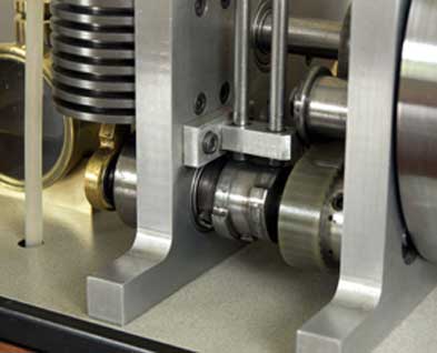
3. The driving system
For coupling the two crankshafts and the flywheel I applied a tooth belt again. The arguments for that were the same as with my Linford Two stroke engine:
-Bridging the distances between the crank shafts and the flywheel is easy and flexible with a tooth belt. The freedom for the other dimensioning is almost 100%, which is important in this case since the distance between the crank shafts is relatively big. Gear wheels should have big diameters for this. Moreover, the construction with a tooth belt becomes lighter and much more friendly;
-A tooth belt runs quietly with few friction and it don't need greasing;
-The cog wheels for a tooth belt are easy available in all kind of measures. Making this wheels yourself (if necessary) is rather easy too, this in contrast to gear wheels for which you need special module cutters and much more workmanship and experience.
The tooth belt must be under a light tension. This can be easily done with a small adjustable tension wheel of which the side flanges keep the belt sidewise in place also.
Because there is no 1 to 2 distribution with this Scuderi the cam discs for driving the valves could be placed directly on the crank shaft for the power piston. I mounted the cam disc for the spark ignition on the other crank shaft for the compression piston that turns around with the same speed.
4. The fuel system
I also use here my positive experiences with ball valves and the Petrol Vapour Carburettor.
The principle of one-way ball valve between the two cylinders is the same as for the approved design on most of my engines but there are two differences:
- Here a spring is pressing the ball on its seat. The pressure must be low: you just must be able to lift the steel ball from its seat by firmly blowing on the bottom connection with your mouth; which is about the same as air pressure of about 0,5 ato.
- I used a bigger steel ball here with diameter 7mm instead of 4,8mm. With this bigger sealing surface the lifting force on the ball from the compressed gas mix is bigger also, so I could make the balance between the spring pressure and the compression pressure less critical.
Some calculations learned me that the compression volume between the two cylinder must be about 8cc, but that is not very critical.
5. The spark ignition
For the spark ignition I used the classic circuit with an ignition coil, for which I bought a rather small specimen at an auto car demolition firm. I abandoned the use of the sympathetic method with a piezo cristal because the spark energy with it appears not big enough to make a reliable ignition for two stroke engines. Why this works perfectly with my former four-stroke engines and not for the two-strokes I still don't understand.
Don't use the small high tension coils as nowadays are used in modern motor bicycles; they mostly have specific electronic power supply from a generator on the fly wheel axis and make a weak spark on low DC voltage or no spark at all and sometimes they burn out on that DC voltage.
Although the high tension coil is much bulkier than the sympathetic piezo my frustration about the disadvantage of the high tension coil is limited because one can easily build it in the wooden base as well as the breaker switch for the primary coil current. For the 12V power I use the battery of my hand drilling machine in a self made holder which can be connected with a electrical plug in the wooden base. May be not the most creative solution, but efficient and very reliable.
Because the geometries of the ignition coil and other circuit elements will depend on its availability this construction is not part of the drawing plan. In fact building-in is more improvisation on the spot and it is rather difficult to put on paper. But it will be no real problem for anyone who wants to build this engine I suppose. The electrical ignition circuit is given on sheet 10 of the drawing plan and also a picture how I build the coil in the wooden baseThe process timing
The timing for the diverse parameters is very typical for this Scuderi, mainly due to the very short intake time for the compressed gas mix in the power cylinder. After extensive experiments I found the optimum adjustments as given below and on sheet 10 of the drawing plan with what the engine is running very nice and reliable.
The angle of rotation is measured on the fly wheel when it is turned counter clockwise, where 0° is defined as the highest position (TPD) of the power piston with the two valves.0°: Power piston at TPD; the exhaust valve closes and the intake valve start openening at the same time, starting the injection of the compressed fresh gas mix in the volume between the two cylinders into the power cylinder.
50°: The intake valve closes and the spark occurs at exactly the same time; this is rather critical !
170°: The exhaust valve opens, starting the exhaust stroke.
360°(=0°): The process cycle repeats.Video:
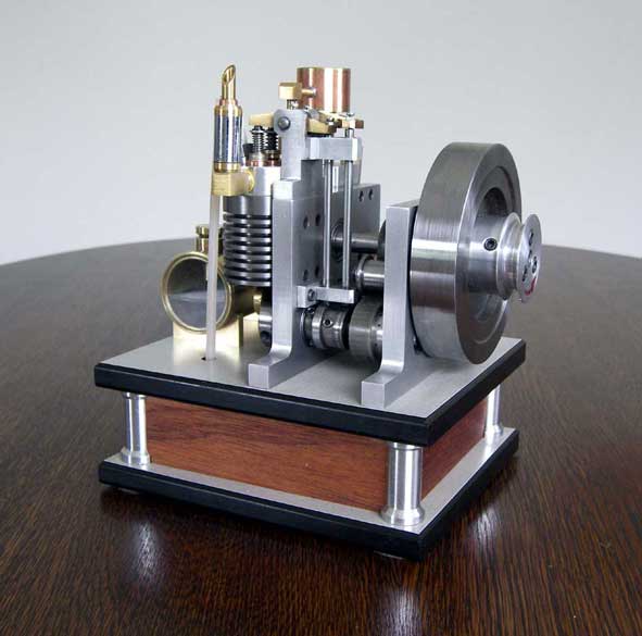
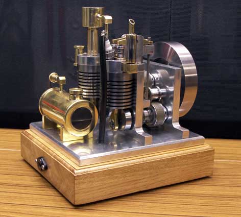
Finally
At first glance this little engine may look somewhat complex but I dare to say that my everlasting strive for simplicity is rewarded again in this case. All parts are easy to make with standard lathing and drilling work out of standard materials. May be except for the pearlitic grey cast iron that you can not obtain on every corner of a street. But it is worthwhile to take the effort to find it because of its special properties that work out very well in this case.
Starting up this engine cab be done with a loose belt around the pulley on the fly wheel and around a similar pulley in the head of your hand drilling machine. Once all adjusted well it is possible to start the engine with a firm push to the fly wheel by hand.
This Scuderi engine is really running "like a charm" and you can regulate the speed anywhere between 500 and 2000 rpm with the adjuster on the petrol vapor carburetor.Drawing plans
I made a CAD drawing plan for this Scuderi engine that is available for any-one interested; for a request click here.
Replica Henk van Beek:
Very nice replica made by
Gerard Versluys:
Replica made by:
Jan Dirk Verstraten