The idea
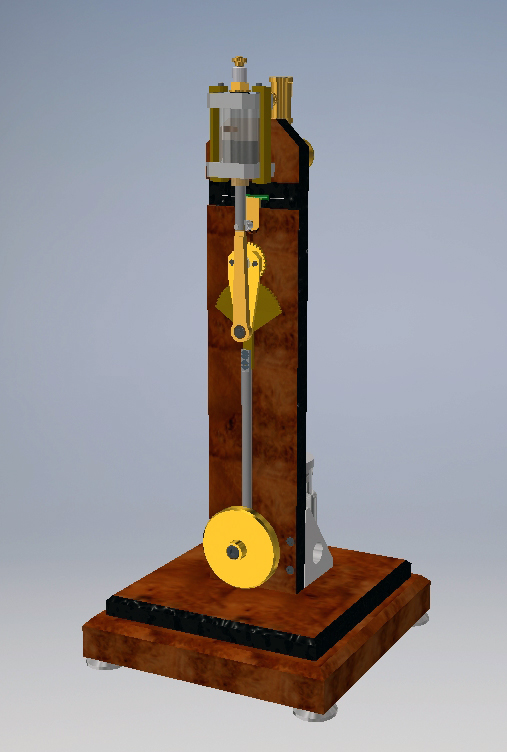
I thought that it would be fun to design a 2-stroke engine in which the piston is held in motion by a pendulum instead of by a conventional flywheel. It should have the looks of a clock in which the pendulum is not powered by a spring, but by a working piston which runs up and down in a glass cylinder as a result of a two-stroke combustion process.
Not more than a gimmick because it is not intended to drive something or that you can see what time it is. So rather useless in the practical sense But I always like to walk on untrodden paths because that gives me a kind of adventure feelings with more or less challenging outlooks.
I made a design where I again applied various sub designing and tricks with what I have had good experiences with several earlier made combustion engines. Completely new here is that only a flywheel and crankshaft are lacking whose functions are taken over by a pendulum and a gear rack system.
History
Already in 2015 I made the first design, but I couldn't let it run in spite of numerous start-up attempts and many experiments to determine the cause of the failure. I was thrown back and forth between the feeling that I was missing something or that it was fundamentally unfeasible to keep a 2-stroke engine running at such a low speed. Because I could not find out why it turned out to be a failure I finally gave up, something that I do not very quickly. So the project disappeared in the refrigerator. However, it kept gnawing at me that I could not successfully implement a design that would have to work on paper. When this project came up three years later (January 2018) during a contact with my friend and ex Philips colleague Jos he convinced me to get it out of the fridge to try it again. He proposed to also involve a second former Philips colleague Jan. It are these two men who have stimulated me for about 3 months to keep going to the bitter end. And I needed this support because I worked on it for about 6 weeks, where I had to make 5 different versions to finally achieve the desired result. Without "the soothing breath of Jos and Jan in my neck" I probably would not have sustained these 6 weeks for which I owe them gratitude. From the first four versions I actually only learned how not to do it, but I gradually discovered more and more where the sensitivities were, and there were quite a lot of it. In fact, they could all be traced back to the fact that a pendulum simply has a considerably less floating effect than a rapidly rotating flywheel. It would be going too far here to explain all the experiences during all those weeks in detail, also because a considerable number of them turned out to be irrelevant in retrospect. The main sensitivities and the resulting measures that ultimately led to the good result will be discussed below.The design
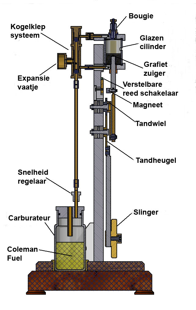
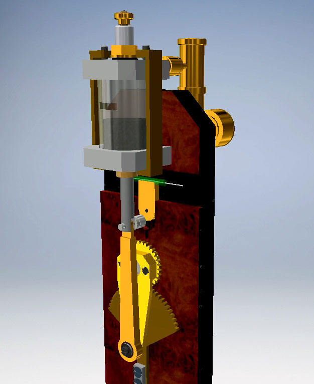
The below figures illustrate the design:
Figure 1
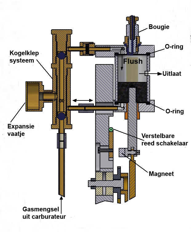
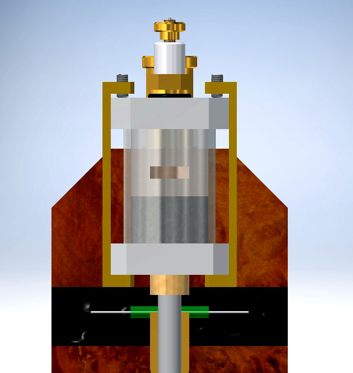
Figure 2
Figure 3
The process principle.
The rigid piston shaft of a small 2-stroke engine is connected by means of a connecting rod to an eccentric attached to a small gear. This gear drives a circular gear rack that I made of a two times larger gear. The transmission ratio of these two gears is therefore 2 to 1. The pendulum is attached to this gear rack. This construction ensures that the piston of the 2-stroke engine moves up and down as the pendulum oscillates back and forth. In both the left and right highest position of the pendulum, the piston is also in its highest position with the maximum compression occurring above the piston. At that moment, the spark on the spark plug is also generated, which ignites the gas mixture above the piston. The next working stroke of the piston causes the pendulum to be pushed back to the other extreme position. There the combustion process repeats itself, so that the pendulum is pushed back to the opposite extreme position. This creates a continuous pendulum movement as long as the 2-stroke process runs smoothly and at least regularly. A small Neodymium magnet is mounted on the pivot point of the piston shaft and the connecting rod, which means that it moves up and down together with the piston shaft. A height-adjustable reed switch is closed shortly by this magnet when the piston has reached its highest position. At that moment the reed switch triggers a miniature spark system that I made of an electronic circuit from a gas lighter; Click here for the description of this "Blokker" spark system. This spark ignition system is mounted on the back side together with the 1,5 volt battery supply.
In fact, the height setting of the reed switch here determines the maximum compression because at the moment of the spark the gas mixture ignites and the piston is then immediately pushed down. It turned out to me that the height setting of the reed switch is one of the most critical sensitivities of the entire system. If the reed switch is set too high, the crank will run at such a high compression that it can no longer make its full stroke. If the setting is too low, the gas mixture ignites too early, as a result of which the power of the work stroke becomes too low to allow the pendulum to make its full strokes. The margin for this reed setting is very small, but once the correct height of the reed switch is found, this is not a problem.
*************************************************************
Unfortunately this gas lighter with this specific circuit is almost nowhere for sale any-more as far as I know. A good alternative is a ready-made small electronic spark system for model engines, for sale at AliExpress for about 16 Euro, search with:
aliexpress spark igniter model engines and then choose the circuit below:

It seems to mee a good idea to make a small extern unit with this circuit once, which can be connected then to any model combustion engine.
**************************************************************
The 2-stroke unit
In fact, I have taken over the 2-stroke concept from the "Pressure-controlled 2-stroke Sabine"; click here for the relevant page. A system with two ball valves and an expansion vessel automatically provides suction of the fresh gas mixture from the carburetor, compressing it into the expansion vessel and flushing the cylinder as soon as the piston passes the outlet opening in the cylinder in its lower position. In contrast to the standard 2-stroke process, the fresh gas mixture is injected at the very top of the cylinder instead of through an inlet opening in the wall of the cylinder opposite the outlet port. The flushing process at the top of the cylinder head is much more effective with this ball valve system. The cylinder is made of glass that I cut from the cylinder of a 20ml Optima Fortuna syringe. This heat resistant borate silicate glass has a relatively thick wall of 2 mm and the internal diameter is extremely accurate with an out-of-roundness of the order of 0.01 mm. This made it possible to make a graphite piston that runs virtually leak-proof in that cylinder with negligible friction. The cylinder is tightly clamped between two O-rings lying in grooves in the upper and lower lid of the cylinder, see figure 3. According to my experience the combination of a glass cylinder with a piston of graphite is ideal for this type of combustion engines: the bore in the cylinder does not have to be made by yourself, is extremely accurate in diameter and is super smooth. The graphite piston can therefore be made in that cylinder with a very good fit and runs virtually without friction therein without any wear. An additional nice thing is that the ignition is nicely visible through the glass wall when the room lighting is somewhat tempered. This can be seen nicely on the video at the top right and bottom of this page. The rigid piston shaft runs up and down through a slide sleeve in the lower lid, where it is important that the fit is so accurate that, on the one hand virtually no air leakage occurs and with low friction, on the other hand. It is my experience that this can best be realized by using standard shaft material for the piston shaft with an accurate diameter and with a matching standard slide sleeve that is pressed into the bottom lid. I used a sliding sleeve that is provided with a thin Teflon coating, but any other sleeve with a nice (H6) fit will also suffice.
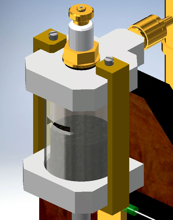
The proper assembly of the components of the 2-stroke unit initially cost me some trouble because the center line of the piston with its shaft must coincide exactly with the center lines of the top and bottom cover because otherwise the piston will get stuck in the cylinder. Initially I had screwed both cylinder covers to the vertical mounting plate but this led to over-determinations of the various sizes. If the covers were only one hundredth crooked on each other or not centrally with respect to each other in the horizontal plane, the piston would immediately get caught in the cylinder. To solve this problem I have made the diameters of the O-ring grooves somewhat oversized so that the cylinder got a few tenths of a millimeter of clearance in the horizontal plane. Furthermore, I no longer screwed the upper cylinder plate to the mounting plate but with two metal brackets clamped against the cylinder with the cylinder in between , see figure 4 below.
Figure 4
During the stepwise tightening of the two setscrews I have constantly moved the piston up and down so that the lines of the various parts look for each other so that the piston runs smoothly up and down and the leak-proof seal against the O-rings is established.
The carburetor.
The "Spice jar" carburetor used here is a variant of the universal "Petrol Vapor Carburetor" with otherwise the same principle. This version is a strong simplification where I used a small spice jar as a petrol reservoir. At the top it is closed by a metal lid in which there is a pipe for the intake of the outside air and a second pipe for the outlet of the gas mixture from this carburetor with a regulator for adding extra outside air; it simply can not be easier. This vertical variant also fits better in the relatively narrow and high design of this "Pendulum 2-stroke". I use Coleman Fuel as fuel. It is an extra refined petrol type that is virtually odorless and contains fewer different hydrocarbon components, so that the composition remains somewhat more stable during use than with motor gasoline. This Coleman Fuel is mainly used as fuel for camping equipment and is therefore for sale at every Camping shop.
The pendulum construction.
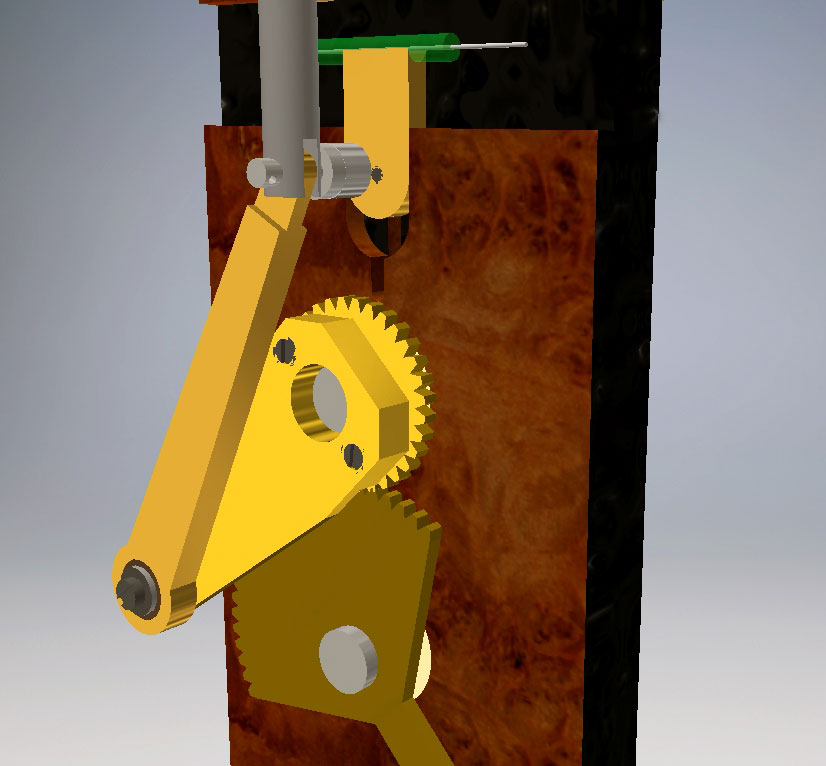
The pendulum is mechanically coupled to the connecting rod of the piston via a system with a gear and a gear rack, see figure 5 below:
Figure 5A strip is attached to the upper smallest gear, the connecting rod for the piston shaft being mounted at the end of the strip. Thus this behaves as a kind of crankshaft. The length of this strip mainly determines the torque (force x arm) that is applied to the small gear. Initially I had made that length relatively short, so the 2-stroke engine had trouble getting the system moving. I then made the length of the strip twice as long and that turned out to be a major improvement. The small gear runs over a round gear rack that I made of a gear from the same set that I found in my junk box; who keeps what has what. The transmission is 1 in 2, which largely determines the swinging stroke. A fairly arbitrary choice that turned out to be quite suitable afterwards but may not be entirely optimal. The pendulum is attached to the gear rack from which I have removed the part that does not participate in the drive. In my opinion this looks better than a complete gear; furthermore, this has no functional meaning.
The interplay of forces between the 2-stroke unit and the pendulum.
The interplay of the whole system is pretty complex if you ask me. There are quite a few physical and mechanical parameters that determine the motor behavior such as:
- The force that occurs during the working stroke of the 2-stroke engine. This is largely determined by the moment the spark occurs in the 2-cycle cycle because the height of the compression depends on the piston of the gas mixture. The moment the spark comes, the piston will not go up any further because the gas mixture ignites at that moment causing the piston to be pushed back down immediately;
- The length of the strip on the small gear that determines the torque applied to this gear;
- The transmission ratio of the small gear and the rack which, among other things, determines the pendulum stroke;
- The length of the pendulum. This only partially follows the well known pendulum formula because this pendulum is mechanically coupled to the 2-stroke unit with decelerating compression pressures, both above and below the piston. This is therefore not a completely free-running pendulum for which the pendulum formula applies;
- The volume of the expansion vessel that determines the compression pressure under the piston;
- The height of the outlet hole in the cylinder, which determines, among other things, the amount of fresh gas mixture which is drawn in under the piston at each stroke;
- The weight of the pendulum. This is mainly important for the driving force (inertia) that the engine must help through the laborless phases. If the weight is too low, this inertia is insufficient for this, a too heavy weight will cause an incomplete stroke of the pendulum. I determined experimentally that a weight of about 100 grams is the best choice.
- The setting of the carburetor that is pretty critical in this case, I do not know why.
At least, it was not possible for me to relinquish calculations on all these dependent or non-dependent parameters to bring about the optimal system. Some choices were therefore emotional, others where a result from the large series of experiments that I carried out. If only one parameter was set incorrectly, the thing did not work or badly and then it was difficult or impossible at that time to examine the sensitivity of the other parameters. All this means that in my opinion the result achieved is satisfactory but almost certainly will not be completely optimal.The result.
Unlike with a fast revolving flywheel it was predictable that the engine would stop immediately if there is even a single moment where there is a disruption of ignition of the gas mixture. I therefore had the intention to be satisfied if this Pendulum 2-stroke would run continuously for at least one minute without an intermediate restart, the longer the better of course. I succeeded in the end, although this is not always the case. But it also happened that the engine ran continuously for 3 minutes. All in all reason to end the project for now or for the time being. One more restriction: the engine must be attached to the surface in some way or another because otherwise it will swing back and forth on the table in such a way that the pendulum movement is disturbed too much. Below the video that made the Slinger 2-stroke in the situation it is now:Video:
Drawing package.
I have made a CAD drawing package of this model that is available for every interested person; click here for a request.

Beautiful replica by
Huib Visser: