An easy-to-make 4-stroke Otto model engine
The idea behind this design.
My first IC model was an Atkinson 4-stroke engine; see the concerning page. A very exciting engine but its mechanical behaviour is very tempestuous, due to the multiple reverse and abrupt motions of the spectacular but rather complex driving system for the piston. I had to make great efforts to domesticate this engine to an acceptable behaviour, but at the same time this learned me a lot about the principles and the peculiarities of combustion engines and adjusting the very different parameters.
With this experience and knowledge I considered myself able to design a new 4-stroke stroke engine. This time it was my explicit purpose to obtain a model engine with an exemplary quiet and friendly behaviour. In addition to this major purpose I had some other intentions:
1. A transparent and good looking model, as close as possible to the primary principles of a 4-stroke internal combustion engine. It must demonstrate the four engine strokes as clear as possible, even for not technically orientated spectators;
2. No more parts than strictly necessary to run the engine;
3. A minimum of rotating, oscillating or other reverse movements;
4. Direct as possible driving system for all moving parts;
5. All mechanisms well visible, open and bare;
6. No complex forced cooling and/or lubricating systems;
7. No difficult fabrication techniques like casting, molding, accurate grinding, cog- or chain wheels, etc. It must be possible for every "moderate" model builder like me to make this engine with simple standard lathing and milling work and from standard bar stock materials.
So, my goal was to design and make a honest, reliable, nice and quiet running 4-stroke internal combustion engine, other than a complex and high power machine.The basics of this design
To gain my object I assumed that the Otto principle should be a good starting point for this 4-stroke combustion engine. Almost all of the motorcar engines are based on this Otto principle. Typical for the Otto is that the piston is driven by a singular crank, which is a considerable more direct and simpler construction than the complex crank system of the Atkinson engine. This should be the key for a much better dynamic behaviour. Here the crankshaft must make two revolutions for the four piston strokes: the gas intake-, the compression-, the power- and exhaust stroke. The shaft for the valve- and ignition cams must rotate with half the speed of the crankshaft. This is realized with a 2 to 1 distribution mechanism between crankshaft and camshaft.
So, the big difference with the Atkinson is the very direct driving of the piston and the driving of the valves and ignition arrangements. For the rest the four stroke principle is the same as with the Atkinson, so that I could copy an important part of that design.The working-out of this Otto engine design
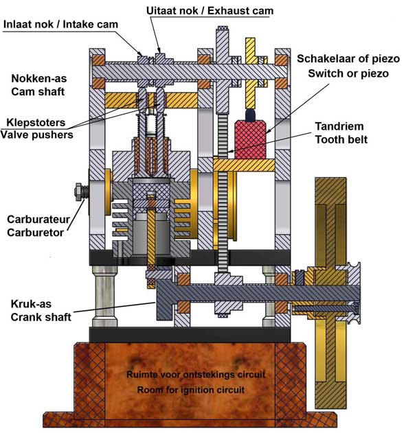
Below the design sketch for this Otto engine.
1. The cylinder/piston combination.
For the cylinder as well as for the piston I used pearlitic grey cast iron. In this case this material is at least highly preferable, may be even conditional. The thermal expansion of cast iron is very low and in any case equal for cylinder and piston. Together with the fact that it is more or less self-greasing due to the relative high carbon grade, it prevents jamming of the piston, even without forced oil greasing!
Furthermore cast iron is highly temperature resistant and working up is rather easy. If the surfaces of the piston and the cylinder bore are made accurate and smooth there is no need for a piston ring.
Although forced lubricating is not necessary it is advisable to put an oil droplet through the spark plug hole now and then to keep the piston and cylinder surfaces "in good condition". This is especially needed before storing the engine for a longer time because cast iron is somewhat rust sensitive when the surface is completely grease free.2. The camshaft and its driving system.
I choose for an overhead cam shaft for the reason that the cams can drive the valves in the most direct way: no intermediate cam lifter arrangements with pushing rods and oscillating tumblers. Only short pins in gliding bushes between the cams and valve stems to avoid transverse forces on the valve stems. The lengths of these pins are made in such a way that there is some tenths of a millimetre left between the pins and the cams when the valves are closed. May be a hazardous construction, but it works very well !
The ignition cam is on the same cam shaft. All three cams are fixed with screws on the shaft, so they can be adjusted in every position within the four stroke cycle. The cam shaft is driven by the crank shaft with a synthetic timing belt. The wheel on the cam shaft has 72 teeth, the wheel on the crankshaft has 36 teeth. This kind of small and flexible belts and wheels are available everywhere. Every other flexible timing belt is OK as long as its circumference is anywhere between 400 and 450mm. The same counts for the cog wheels as long as they have about similar diameters and the ratio of teeth number is exactly 2 to 1.
With such a timing belt it is easy to bridge the distance from crankshaft to camshaft. Furthermore it provides a very smooth and noiseless drive without the need of greasing it.3. Process timing schedule.
The time cycle measured on the camshaft is as follows:
0º: Upper position of the piston (TDP), the intake valve is opening;
70º:The intake valve closes; so 20º before the lower piston position (BDP);
90º to 180º: compression of the gas mix;
180º: Upper position of the piston (TDP); ignition spark (or a fraction earlier); ignition gas mix and start power stroke;
250º: the exhaust valve opens; so 20º before bottom piston position (BDP);
270º: Piston in bottom position (BDP); start exhaust stroke;
355º: the exhaust valve closes; so 5º before TDP;
360º(=0º): Process repeats.
I found this time cycle to be optimal at relative low engine speeds, which I prefer for this kind of model engines.4. The spark ignition.
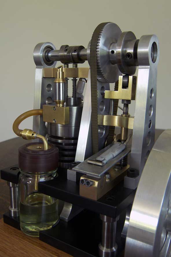
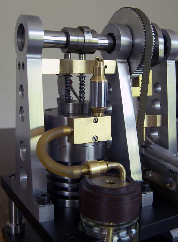
Initially I used a piezo element out of a gas lighter as you still can see on the pictures on the right of this page. But later I used the miniature "Blokker" circuit; see the concerning page for that system.
In case one cannot make this miniature circuit circuit a high tension ignition coil as is/was used for classic auto cars and motor bikes is an alternative. This (much bigger) coil can be build in the wooden base on what there is an electrical plug to connect an external 6 or 12 volt DC power supply for what the rechargeable battery of a hand drilling machine is very suitable. The switch (points) for that ignition circuit must be mounted below the cam disc.
The spark plug is self made; see drawing plan. It contains a Teflon isolator that withstands the combustion temperatures without any problem. This spark plug is easy-to-make and the threads on the Teflon is not only for mechanical fixation but also for the air-tightness at the same time.5. The carburetor.
First I copied the more or less classic carburetor as I used for the Atkinson engine. Provided it is made accurately this carburetor operates reasonable. But it was the most critical part of the engine. The adjustment is rather sensitive, there is a constant risk of "flooding" the engine and carbon soot easy arises on the sparkplug due to incomplete combustion of the fuel mix.
So I was not satisfied with this carburetor and insiders told me that is was hardly possible to implement substantial improvements for this basic carburetor design. That was the reason I designed a complete new alternative for making a mix of air and 100% molecular petrol vapour instead of fluid petrol droplets with the optimal ratio of about 1 to 14 (petrol/air). The performance of this carburetor is astonishing well with multiple advantages (see also the concerning page):
- Always 100% molecular petrol vapour in the gas mix. Consequently never any fluid petrol droplets in the cylinder and, as a result, no carbon soot or wet spark-plug, due to incomplete combustion;
- The ideal ratio petrol vapour/air of 1 to 14 is easy obtainable by adjusting a simple regulator for adding extra air. This very homogeneous gas mix provides for a perfect running engine;
- The engine is provided immediately with the right gas mix, so starting-up is very reliable and fast without choking. Choking is actually not possible with this system;
- In fact it is no longer possible to flood the engine; at least haven’t succeeded in doing that so far;
- The speed of the engine can be well regulated with the regulator for adding extra air on the rear of the tank;
- This carburetor design is very simple: no venturi, no petrol jet with needle, no accurate dimensions, no chance for false air- and/or petrol leaks;
- This carburetor may look somewhat bigger than the classic one, but the contrary is true: in fact it is only a small arrangement, integrated in and on the petrol tank;
- This carburetor cannot be overheated because there is no heat conduction from the cylinder to it. The length of the (rubber) connection tube to the intake manifold is not critical at all. I didn't notice any difference between 10 and 50cm tube length! The location for this carburetor is therefore free to choose;
- Regulation of the petrol level is irrelevant;
- No risk of stoppages; there are no narrow flood gates and possible contingent dust particles remain visible in the petrol tank. They disappear while draining the tank at the end of a demonstration;
- Petrol consumption is minimal; not more than necessary for the energy to be created;
- No chance for petrol leaks to the outside of the carburetor, and therefore safe and without unpleasant smells.
I now use this carburetor for all my stationary IC engine, so also for this Otto.
Remark: the carburetor on the pictures is a variant of the standard carburetor as on the drawing plan. I made this from a spice jar by way of experiment.6. The flywheel
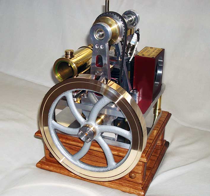
The flywheel must have a fair-sized mass weight because this engine design assumes relatively low revolution speed. The dynamic energy of a bicycle type flywheel is E=½mw²r² where m is the mass weight, w is the radial speed and r is the radius of the wheel. The flywheel of this engine is made of steel with a diameter of 150mm and a width of 20mm. The mass weight is 1,2 kg and the dynamic energy is about 2,6 Nm at 300 revolutions per minute. With this flywheel it is possible to run this engine with a speed as low as about 200 revolutions per minute.Video:
Some characteristics
- Both the diameter and the stroke of the piston are 24 mm. The cylinder volume is also about 12cc.
- I choose for a relatively low compression ratio: about 1 to 4. At higher compression I assume more difficult start-up and higher cylinder temperatures. The engine power could be higher in that case but, as I said, a high power was anything but my intention.
- The revolution speed can be adjusted between 200 and about 2000 RPM but I never exceed 1000 RPM because I don't like the behaviour at very high speeds.
-This engine runs on standard petrol Euro 95 or 98 for motorcars. One can "Coleman Fuel" also which is preferable because it contains less different hydrogen carbon components and it has no bad smells.
- The engine can be started with a loose belt around the pulley on the crank shaft and around a similar pulley in the head of your hand drilling machine. Well adjusted the engine can be started also with a firm push to the fly wheel by hand.
- The cylinder temperature don't exceed 110º Celsius after 15 minutes runtime.
Drawing plan
For this Otto engine I made a CAD drawing plan that is available for every-one interested; for a request click here
Tips for adjusting the Otto engine and/or in case of troubles:
1.Starting-up the engine.
The engine can best be started with a hand drillmachine that drives a pulley on the fly wheel shaft in one way or the other. If everything is set up properly the engine will start after a few seconds, after which the handdrill machine must be taken away from the pulley. The engine can also be start-up with some manual pushes at the flywheel when the engine has run well previously.
2,The petrol vapor carburetor.
It is important that during this start-up the carburetor is adjusted well; please read the instruction portion of the drawing plans of this carburetor .
Especially with fresh auto car gasoline the start-up may be a bit sensitive. One often tend to make the mixture richer by decreasing the amount of extra air with the adjuster at the outlet of the carburetor but that is absolutely wrong: always first turn the controller for the extra air on the carburetor completely open during starting-up with the hand drill and then decrease this extra air gradually while turning the engine with the hand drill machine until you hear the engine is taken over. Around that carburetor setting the engine will run optimally, and the speed engine can be controlled by changing the extra air somewhat more or less. After a few minutes running, the engine speed can decrease gradually because the most volatile component of the gasoline evaporates. Then one must reduce the amount of additional air somewhat again until the engine has regained the desired speed. After that the situation will become stable.
3. The two valves.
Both valves should close properly because otherwise a too great a loss of compression occurs or false air is sucked during the intake of the fresh gas mix from the carburettor. See for making the valves properly sheet 4 of the drawing package. Most important is that the centre line of the valve stems are exactly aligned with the centre lines of the valve seats. If these centre lines are not aligned well it is in fact no longer possible to let the valves close properly by grinding them on the seats. Grinding the valve on their seats is only necessary if there is still an unacceptable leak detected or suspected .
The compression does not need to be very high: 3 to 4 Bar is sufficient here. The compression is OK when the engine just stops against the compression after a firm manual push to the fly wheel.
4. The process timing.
With the process timing as described below below (measured on the cam shaft ) the engine runs perfectly;small deviations can be allowed:
0 °: The piston is in the first upper position, the inlet valve starts to open;
70 °: The intake valve closes, so 20 ° before the lower piston position ;
90 °: The piston is in the lower position and the compression stroke begins;
180°: The piston is in top position again (maximum compression) and the spark ignites. The spark can come even a little bit sooner if necessary. The gas mixture ignites and the power stroke starts;250 °: The exhaust valve opens, so 20 ° before the lowest piston position;
270 °: The piston is back in the down position and the exhaust stroke begins;
355 °: The exhaust valve closes, so 5 ° before the intake valve starts to open again.
360º(=0º): Process repeats.
Sometimes it is said that the outlet valve should close shortly after the inlet valve opens. This would have a beneficial flushing effect. But I 've never found this: so first close the exhaust valve and then open the inlet valve immediately after that.
5. In order to ensure that the valves close well, there must be a slight gap (0.3 to 0.5 mm) between the little valve pushers and the low circumferential part of the cam discs, so during the time the valves must be closed. If the pushers even gently touch the cam disc during that period too much compression will be lost. It is easy to overlook something like that, at least it happened to me. So please check if the pushers don’t touch anywhere on the whole lower circumference part of the cam discs!
6. The valve springs better can be somewhat too tight than too light. The cam discs can easily overcome these spring forces. With too light spring the valves don't close enough and/or will start floating. I made my springs from spring wire with a diameter of 0.6 mm and they have about 17 turns;
7. The valve stems should fit very well in their bronze bushings. A too large leak along the valve stem cause an excess of false air during the intake stroke. In principle it is possible to add a tight-fitting rubber O- ring over the valve stem on the outside with a spacer ring on it on what the spring is pushing the O-ring against the end face of the bronze sliding bush. In that case one must shorten the spring as much as the height of the O-ring and the metal ring above it together.
A small leak along the valve stem of the exhaust valve can actually do no harm, except that there are some exhaust gases to escape there that will be hardly or not noticed.
8. Also, the spark plug must of course be air-tight . If the thread is made on the Teflon it will normally be air-tight. Put a thin rubber O-ring on the spark plug that seals against the cylinder head.
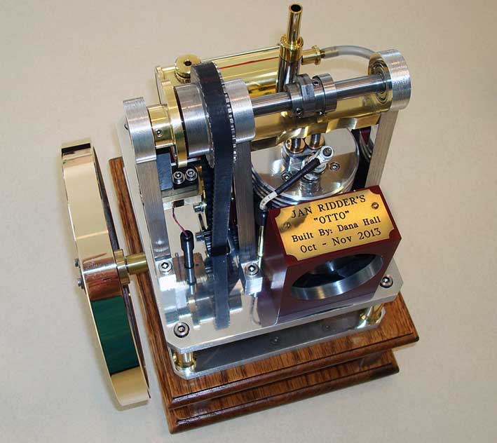
Magnificent replica Dana Hall
Nice replica made by
John van Iersel:
Replica by Paul Iriks:
Nice Replica made by
Jean Francois Brozou:
Nice replica made by
Christobal Jaramillo:
Nice replica made by
Jimmy Vella:
Beautiful replica by
Tiny van den Boom: