Introduction
The main features of this Stirling design are:
1. The displacer is free-running and is driven by a magnet system. The displacer therefore has no shaft to the outside with the advantage that there are no leaks and that the friction is minimal.
2. The model does not have a crank shaft, and the coupling of the displacer with the working piston with the 90 degree phase shift is realized via a sliding magnet below the glass cylinder by means of two little gears with crank pins.
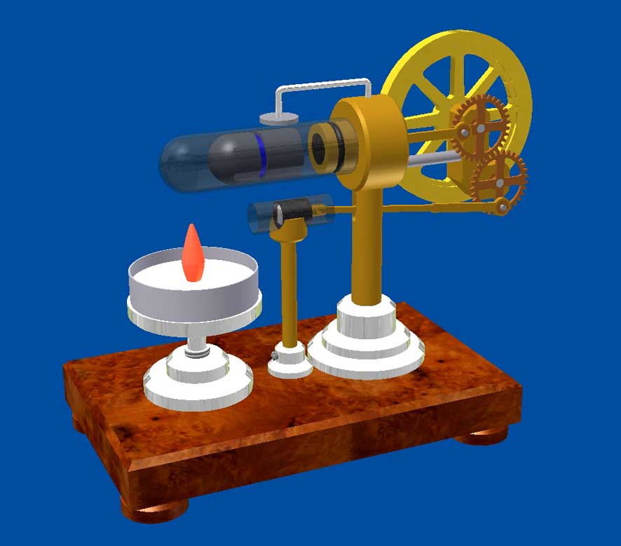
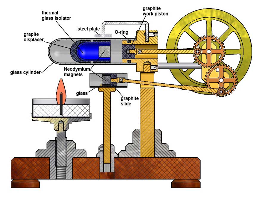
CAD following figures illustrate this design:
Notes on design
1. The displacer.
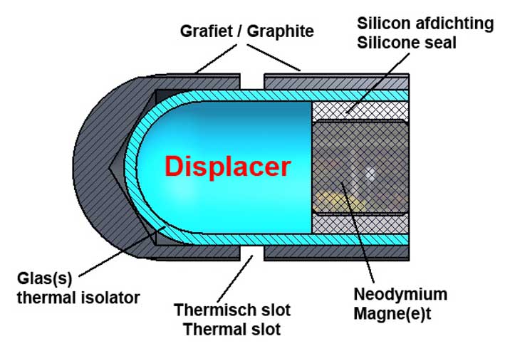
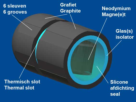
The displacer is made from graphite with a glued-in Neodymium magnet with a diameter and length of 8mm. Graphite has no magnetic properties and will run back and forth in the glass cylinder with very low friction. To further minimize the friction further I have made the clearance of the displacer in the cylinder a few tenths of a millimetre. The displacer also has a six shallow slots in the longitudinal direction along which the warmed respectively t he cooled air is cyclical moved from right to left in the cylinder as is necessary for the Stirling process , see the picture on the right of this page.
The temperature of the Neodymium magnet may not exceed 80 ° Celsius because otherwise it loses its magnetism . Without a provision there a good chance that this will occur as a result of the heat conduction through the graphite. To prevent this I have implemented two measures:
1. The magnet is glued in a glass tube with Loctite 603 and this assembly is glued into the graphite displacer . Because the thermal conductivity of glass is very bad the magnet therefore will stay relatively cool.
2. The displacer is made of two parts, glued with a gap of 2 mm on the glass tube. This " heat slot " will prevent the heat conduction through the graphite up to the part where the magnet is located.
The figure below demonstrates this construction:
The space between the magnet and the glass tube must be filled up with a little silicone sealant, because otherwise the space in the glass tube behind the magnet becomes part of the volume on the right side of the hot cylinder and this will cause a negative effect to the power output of the engine. The easiest way is to first glue the magnet with some little Loctite on the right end of the glass tube and after hardening to fill the gaps between the magnet and the glass with some plumbers silicone kit.
2. The slide magnet.
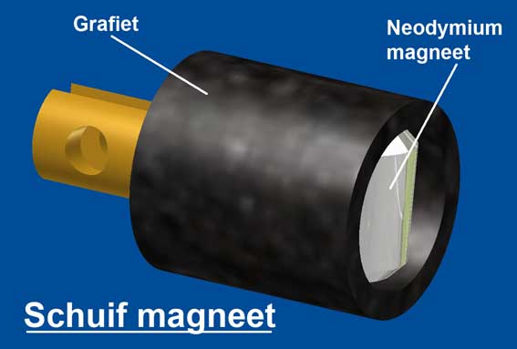
The slide under the glass cylinder moves back and forth and made from graphite and also contains a neodymium magnet which is a little smaller than that in the displacer; 6 x 6 mm. This slide runs in an open glass tube that only serves as a sliding guide with a small clearance of some few tenths of a millimetre clearance to make the friction negligible small. The magnet pulls the magnet in the displacer so that the displacer is running up and down together with the slide and with the same stroke.
I have determined experimentally that the optimum distance between the two magnets must be 20 mm to let the displacer move reliably while the pulling force is not too strong to make the friction between the displacer and the glass is as low as possible.
The figure below shows the construction of this sliding magnet:
The magnet in the slide must be glued exactly in the vertical direction as shown in the figure. The magnet in the displacer will automatically adopt this same direction because the displacer can rotate freely.
The glass cylinder for the slide is glued with acrylic instant adhesive on its support.
4. The working piston.
The working piston is also made from graphite and runs with close fit (less than 0.03 mm) but low friction in the brass cold cylinder.5 . The drive system.
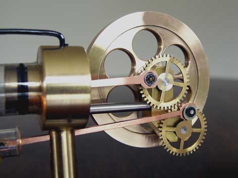
This Stirling has no crankshaft but two gears with crank pins instead. The working piston is coupled to the one gear and the slide with a magnet to the other. The gears must interlocked so that the phase shift between the work piston and the slide magnet (and therefore also the displacer ) is exactly 90° as always is a precondition for a good running Stirling engine.
The crank pins of the two connecting rods are soldered onto the gears (or glued with Loctite 603) with a radius of 8 mm so the stroke of the displacer and also that of the working piston is 16 mm. I have made small ball bearings in the big ends of the connecting rods, although that might not necessarily be needed.
The two driving rods must be neatly aligned to prevent torsion and thus avoidable frictions.
The gears on the flywheel shaft and the shaft underneath are from my collection of gears that I salvaged from clocks. I can not make decent gears because I don't have the module cutters for that and also not the experience. The vertical center distance between the shafts must be equal to the center distance of the magnets in the displacer and in the slider; 20 mm . The diagonal distance should be such that the gears run well together. These two conditions determine the location of the ball bearings in the block for the two axles . So it 's a matter of " Pythagorases " with 20 mm for the one vertical straight side and two times the running radius of the gears as the hypothenuse to calculate the size of the second horizontal straight side.
With home-made or purchased gears of approximately the same diameter, the calculation is accordingly. I assume it most likely that someone else will have the same gears so customizing is needed for anyone who wants to make this engine and that applies not only to the diameter but also the width of the available gears.5 . The glass cylinder.
The glass cylinder for the displacer is cut from a heat-resistant test tube which is fixed airtight and light clamping over a rubber O-ring in the brass cylinder head. The glass cylinder for the sliding magnet need not to be heat resistant because it is not heated.
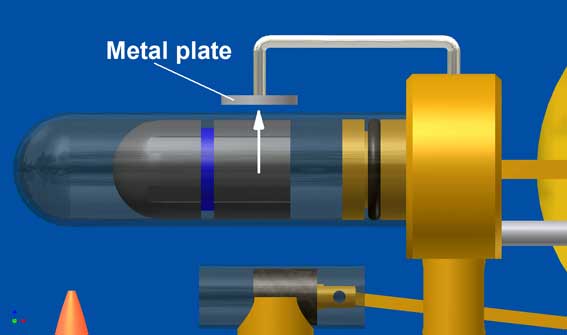
6. The steel plate on top of the glass cylinder.
The displacer is pulled downwards by the magnets and also by the force of gravity against the bottom of the glass cylinder causing some friction with what the engine is not running faster than approximately 200 rpm. It was Huib Visser who came up with the idea to mount a small steel plate above the cylinder that lift the displacement somewhat due to the pulling force of the magnet in the displacer. Depending on the distance of the plate to the displacer the displacer will more or less be "floating" so that the friction will be reduced. The effect of this trick was great: the engine runs 3x faster with this plate with an engine speed of about 650 RPM minute instead of about 200! Thanks to Huib for this wonderful hint.
7. The material for the cold cylinder head and supports.
The cold cylinder as well as the supports for this cylinder and for the glass cylinder for the sliding magnet must be made of non-magnetic material (brass or aluminum), because the movements of the magnets will be slowed down significantly with magnetic material, in particular the sliding magnet.
Finally
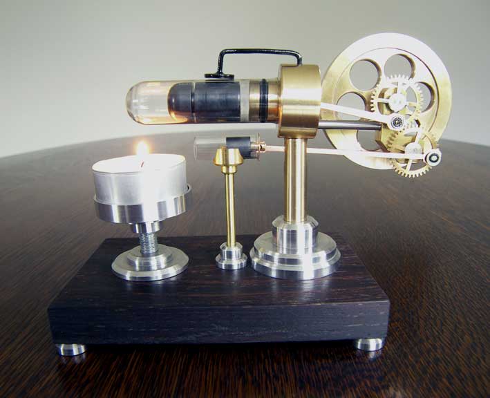
- The engine is really running reliable and perfect with about 650 RPM with a relatively small flame of a tea light. The absence of a displacer axle the adjusted and thus the elimination of friction and leakages there along bears in my view a significant contribution to the very good performance and behavior of this Stirling model.
- I have made a CAD drawing package for this Stirling which is available to anyone who wants to recreate this remarkable model; click here for a request.
Nice version made by Dieter Koerner:
Beautiful version by Huib Visser:
Magnificant replica by Ken Condal:
Magnificant replica by
Ken Toonz