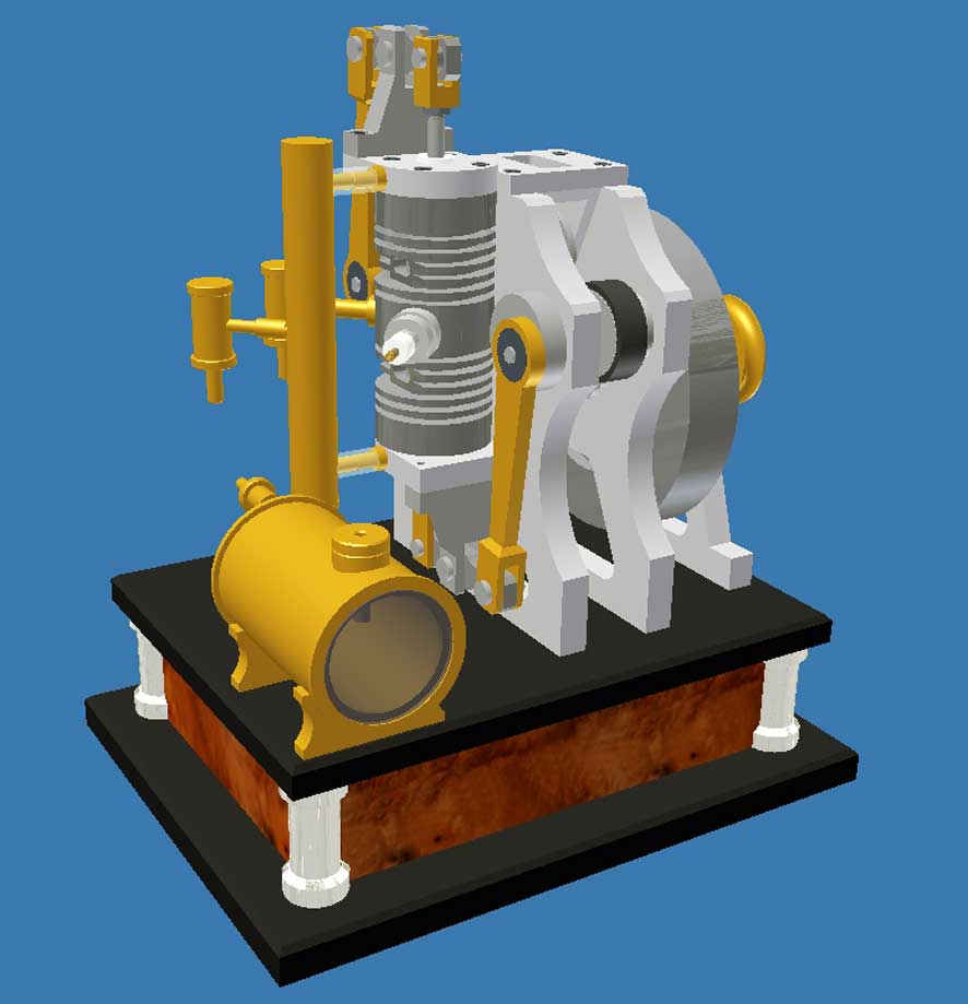
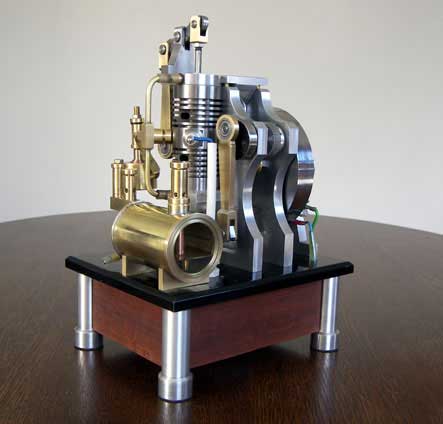
An opposed piston Linford 2-stroke engine
The idea
It was a fellow model builder who inspired me to this idea without realizing he had. He was building a 4-stroke Linford engine with two opposed pistons in one cylinder. The combustion chamber is right in the middle of the cylinder. So, except for the spark plug both the intake and exhaust valves are situated there. In fact, there is very little space for the valves with the rather complex driving system with rockers, pushing rods, camshafts and the 1:2 distribution mechanisms.
To avoid this problem I had the idea to make a 2-stroke engine with opposed pistons instead of a 4-stroke. After all, a 2-stroke engine doesn't have valves at all, so there is no need for the complex driving system and distribution mechanism.
Just before this engine I had build my Pressure Controlled Two-Stroke with its unique and very nice working ball valves and with the Petrol Vapour Carburettor. So I could take over these principles, only making the cylinder twice as long and putting two pistons in it.
But I had to create a solution for connecting the two pistons to the flywheel. That caused me some worries, because the two piston axes come out on opposite sites of the cylinder. Finally I solved this problem by applying a tooth belt for the transmission.
The design
1. The toothed belt construction
Positioning the two crank shafts on the same level was obvious and also exactly in the centre cross plane of the cylinder. The coupling of the two crankshafts has to be in such a way that the positions of the pistons are an exact mirror image all the time. This could be done with gear wheels, but I choose a toothed belt for the following reasons:
-Bridging the distances between the crank shafts and the flywheel is easy and flexible with a toothed belt. The freedom for the other dimensioning is almost 100%, which is important in this case since the distance between the crankshafts is relatively big. Gear wheels would need large diameters for this. Moreover, the construction with a tooth belt becomes lighter and much more friendly;
-A tooth belt runs quietly with few friction and it doesn't need greasing;
-The pinions for a tooth belt are readily available in many sizes. Making the pinions yourself (if necessary) is quite easy, too, in contrast to gear wheels for which you need special module cutters and higher levels of workmanship and experience.
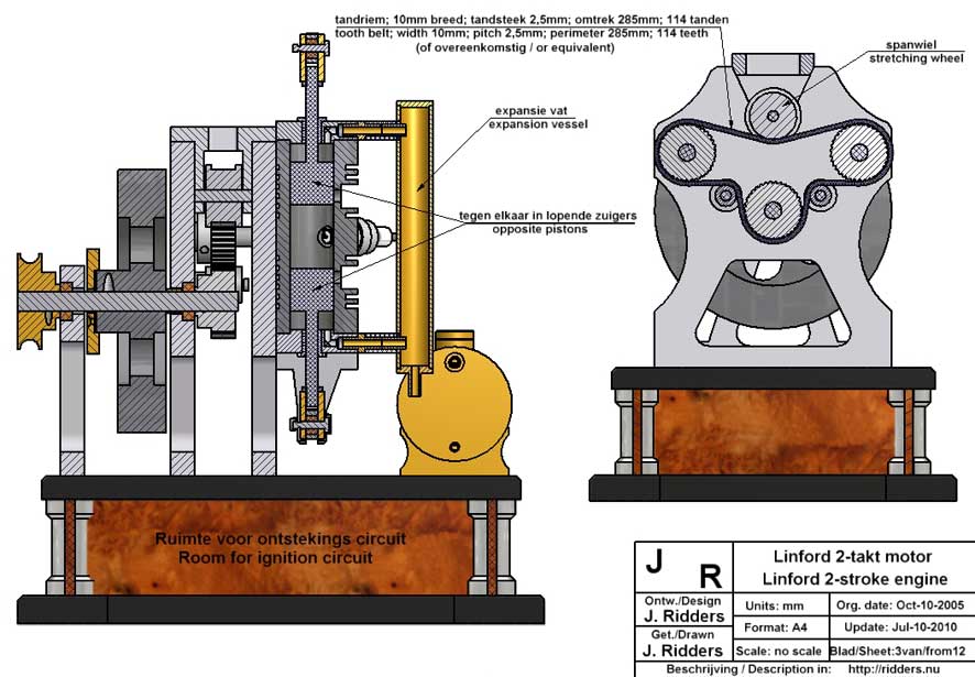
The toothed belt must be under a light tension. This can be easily done with a small adjustable tensioning wheel of which the side flanges keep the belt in place sideways, too.
Also, I came to to the working sketch as shown for the overall mechanics. On that you can see the tensioning wheel and also the two guiding wheels which take care that the belt lies correctly on the circumferences of the pinions.
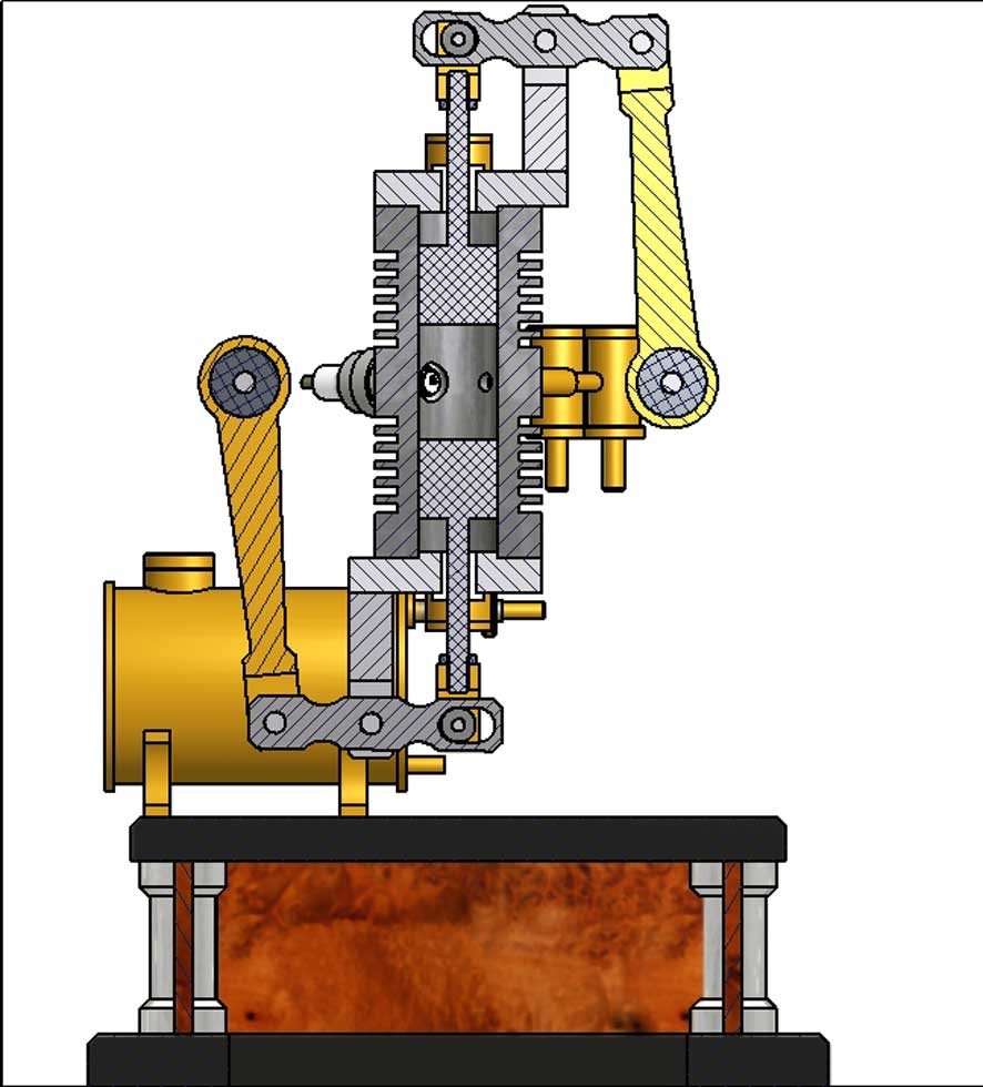
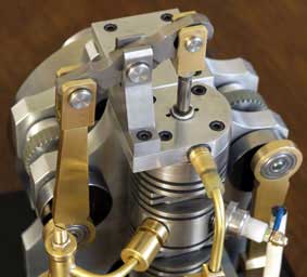
These figures also show in what way the opposed piston rods are connected with the crankshafts by means of rockers and connecting rods. Because the rocker-ends move along a circle segment it was necessary to make slits in them with a small ball bearing on the side where they are coupled to the piston rods that move rigidly vertical.
2. The slide bearings for the piston rods.
Initially I used bronze slide bearings in the cylinder plates for the piston rods. After some running time, however, these bearings wore somewhat, presumably caused by cross forces on the piston rods, this despite the ball bearings in the rockers. As a result the piston rods start tilting and sliding heavily. Also some air leaks occurred between the rods and bearings which is undesirable because the fresh fuel mix is compressed between the pistons and the cylinder plates.
The solution was as simple as it was practical: I replaced the bronze bearings with home-made Teflon ones. It is remarkable how easily, these low friction and airtight rods, now slide in the Teflon bearings - so far without the slightest wear.
3. The cylinder and the pistons.
Except making the cylinder twice as long and putting two pistons in it in stead of one, I could copy the dimensions from my earlier Pressure Controlled Two-Stroke. Again I used cast iron as the material for the cylinder and for the pistons as well.
As with the Pressure Controlled Two-stroke engine I choose again for a rather low compression ratio of about 1:4. It makes starting-up easier and it allows a lower revolution speed. Of course, it is a matter of taste but I prefer reliable starting-up and quite running engines, rather than ‘hooligans’ which are more tempestuous and mostly need a hand drill for starting. The consequence is that the power is rather low, especially with this small cylinder volume.
My experiences with this kind of engine taught me not to use piston rings here, because the friction from them is often to high to overcome. But this is no objection at all if the fitting of the pistons is very accurate, which is not difficult to do, due to the use of cast iron. I succeed in making the cylinder bore accurately cylindrical within 0.01mm and very smooth, using an adjustable hand reamer. While reaming with plenty of cutting oil I turned the cylinder repeatedly around with the same adjustment of the reamer. Then repeating this procedure with a fractionally larger reamer adjustment until I could not measure any diameter difference any more. This treatment looks very much like honing, and with some patience it is about an equal match for it.
I turned the pistons so that they fitted somewhat ‘sticky’ in the cylinder. Grinding the pistons with a fine paste I lapped them in the cylinder until I could detect hardly any friction. The under size of the pistons appeared than to be less than 0,03mm. The result is that the friction is so low that the engine runs "as driven by the wind" while the compression is more than enough. Because of the low and equal thermal expansion of cast iron jamming of the pistons in the cylinder never occurs, even without an oil lubricating system!
4. The fuel system with ball valves and Petrol Vapour Carburettor.
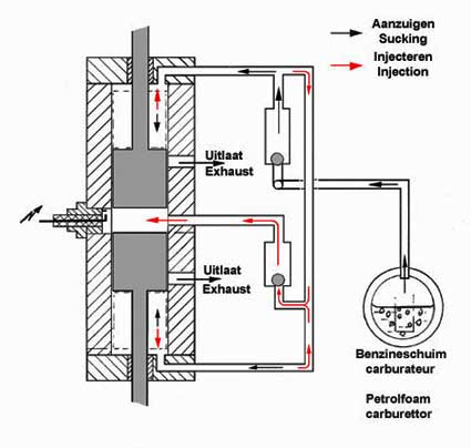
With only small adaptations I could copy the successful fuel system of the Pressure Controlled Two stroke. The supply of the fuel mix is totally automatic and pressure controlled. The sketch on the left illustrates this system; one can find the detailed description on sheet 12 of the drawing plan of the Linford engine.
The sub parts of this system are all brass and can be made with simple lathe work. The 45 degree seats for the steel (bicycle) balls must be made accurate and smooth.
I made pivots in the ball valves with which one can adjust the free moving space of the balls in it, while the engine is running. There is a certain optimum for this free space in the vertical direction: about 0,5. The ball moves with very small clearance in a kind of duct on the pivot. Without these arrangements the ball tends to float in the valve and, as a result, irregular or non-running of the engine.
It is advisable to make all screw fittings air-tight. One can use simply silicone (sanitary) sealant for this. This has the advantage that the valves can be easily demounted if necessary. But take care that the ball seats stay sealant free!
Just as with my first 2-stroke engine a small expansion vessel appears to be inevitable. In fact this volume is a substitute for the volume of the crank case in every ‘normal’ two stroke engine. This volume plays an important role in the pressure and flushing process of every 2- stroke engine. Also the carburettor is a simple and very trouble-free part of the fuel system.
5. The spark ignition.
For the spark ignition I used the classic circuit with an ignition coil, for which I bought a rather small specimen at an auto breakers. I abandoned the use of the method with a piezo cristal because the spark energy of it appears not big enough to make a reliable ignition for 2- stroke engines. Why this works perfectly with my earlier 4-stroke engines and not for the 2-strokes I still don't understand.
However, my frustration with this more bulky solution is tempered because I can build the ignition coil in the wooden base of the engine. For the 12V power I use the battery of my hand drilling machine in a self made holder which can be connected with an electrical plug in the wooden base. May be not the most creative solution, but it is efficient and very reliable.
The spark must arise exact at TDC of the pistons, so at the point where the pistons are as closest together. A margin of +/- 5deg. is permissible. The often heard advice for some pre-ignition is really wrong here, because this engines runs at low (read: nice quiet) speed and then pre-ignition can easily cause back firing.
Because the geometries of the ignition coil and other circuit elements will depend on their availability this construction is not included in the drawings. In fact, building is actually improvisation on the spot and it is rather difficult to put on paper. But it will be no real problem for anyone who wants to build this engine, I think.
Starting up the engine
The fuel for this engine is the normal auto car petrol or, preferably, Coleman Latern Fuel. The cast iron is responsible for the fact that the pistons never jam without oil added to the fuel.
The tank must be filled around halfway which is enough for about 20 minutes running. Generally the model will not run that much because 5 minutes is generally more than enough for a successful demonstration.
This engine needs very little gas mix. Therefore, the restriction for mixing the extra air at the outlet the carburettor tank must be almost open when starting up. Then close this restriction very gradually until you hear the engine taking over (see also the description of this carburettor on the drawing). Once the engine runs the speed can be nicely adjusted between around 150 and 1500 rpm with this extra air restriction. Note that apparently the speed decreases when the fuel mix is richer!
Because builders have to make themselves familiar with the adjustments of the carburettor first it will be necessary, and/or useful, to start up the engine initially with the aid of a loose rubber belt around a pulley on the flywheel axis and around a same kind of pulley in your hand drilling machine. Once conversant with these adjustments one can start this engine with a simple push on the flywheel.
General points and remarks
-It is advisable to put a single drop of oil on the pistons from time to time, for instance through the exhaust openings - not to avoid jamming, but to keep the surfaces of pistons and cylinder in good condition. This is especially useful before storing the engine for a long time;
-This engine has no exhaust mufflers. It is my experience that with my models they hardly have any functional meaning. It looks better of course, but up till now I haven’t found a good solution to give them a place in the limited space near the exhaust openings. I invite everyone to design something nice for that and then showing me that sometime.


Beautiful replica made by
Gerard Versluys: