Introduction
Embroidering on the "Ridders twin piston 4-stroke" I have made a new design based on the same process with 2 opposed pistons in one and the same cylinder. But there are rather big differences such as pistons running in a glass cylinder. Of course very insolent and hazardous but I always like challenging work balancing on the limits on of (im)possible paths. "Easy things can be made by everyone" was the motto of my wise father.
Glass is breakable, but in fact only as a result of a mechanical impacts and this is not the case here. Indeed rather high gas pressures can occur here, especially at the moment the gas mix is ignited at the end of the compression stroke. Then the glass is loaded with circumferential stress but this is surprising high for glass; not much less than for aluminium for instance. The mentioned stress values for glass in divers documents vary strongly depending on the kind of glass and especially if the glass is more or less damaged (scratches). I found stress values between 10.000 kgf/cm2 for intrinsic (undamaged) glass to about 500 kgf/cm2 as a practical save value for more or less scratched glass.
The occurring stress in the wall of a cylindrical tube can be calculated with the form S=(pxr)/t where p is the pressure in the tube, r the radius and t the wall thickness of the tube. For the cylinder that I will apply here the tensile force will be about 160 kgf/cm2 at a 10 Bar combustion pressure, so this is some factors lower than the most pessimistic given values for glass strengths. If I choose for a rather low 3 to 4 bar cold compression the specific combustion pressure will be about 15 Bar max (4.5 x the cold compression) so the tensile stress in the glass will not exceed about 100 Kg/cm2 and glass with about 20mm diameter and wall thickness of 1.5 to 2mm will survive this easily.
The glass will be heated also due to the burning gas mix but the heat content of the airy gas mix is rather low and the temperature transmission to glass is bad also while during half the process time the intake of the fresh and cold gas mix from the carburettor will have some cooling effects. I will use high temperature Pyrex glass that only shows melting signs from about 900 degrees Celsius so this should not cause any problem which appeared to be right in practice.A.The first (MK1) version
1. The global concept
It was my original intention to make the pistons from graphite because it is my experience that they run very smoothly in glass cylinder without any oil lubrication. But for that the tolerance of the inner diameter of the glass tube must be very small; 0.02mm max or less if possible. Almost all tube glass doesn't glass fulfil this requirement and despite intense searching expedition I could not find that kind of perfect glass at first.
The best glass I could obtain at that moment had a inner diameter tolerance of about 0.08mm so I had to use a trick to compensate for the too big clearance between the piston and the cylinder. I put a thin Viton O-ring on a groove in the pistons with such a diameter that the outer diameter of the O-ring in it became about 0.2mm bigger than the inner diameter of the glass to compensate for the clearance. Because the piston itself is not making the air-tight sealing I could make them simply from brass with a 0.2mm smaller diameter than the inner diameter of the glass to avoid jamming because the thermal expansion of brass is greater than that of glass.
To my surprise the friction of the Viton O-rings against the glass is rather low but I put some very thin grease film on it, although I even don't know if that is really necessary.
The glass cylinders are glued in the brass middle piece with Loctite 603 and after hardening at about 50 degrees Celsius during 2 hours in a oven the connection is extremely strong and air-tight.
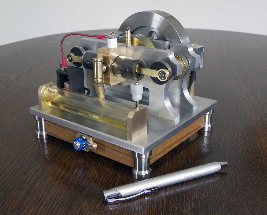
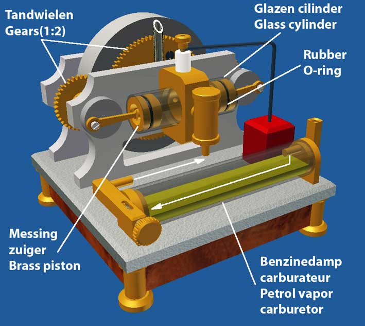
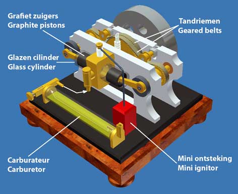
The CAD pictures below illustrate the design of this MK1 version:
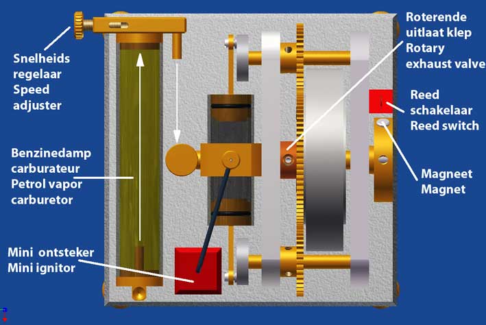
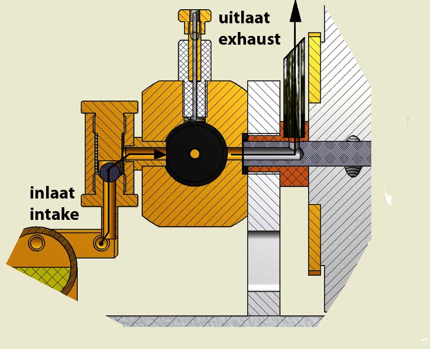
Cross section of the valve systemAs you can see on the cross section view I applied the same intake and exhaust system as for the "Ridders twin piston 4-stroke":
- self-sucking intake of the gas mix from the carburettor with an one-way ball valve;
- exhaust of the burned gasses with a simple rotary valve.
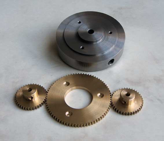
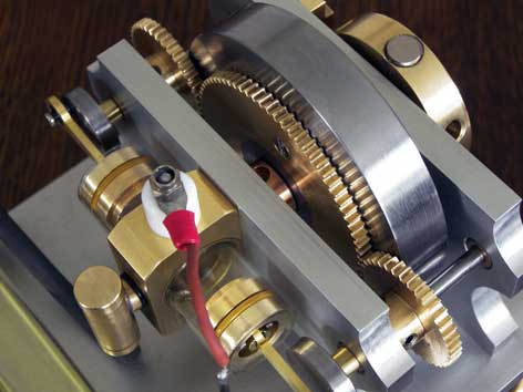
Till than I always use geared timing belts for the driving system, but this time I used gears for the first time. Because the distance between the crank shafts is determined by the cylinder/piston combination and the piston strokes I had to make these gears myself to make them fit within the construction. I don't have the disposition of original module cutters for gears, but I succeeded in making the gears with a rather simple self made 2-cutter and the gears are running not perfect but acceptable in each other, a little bit to my (pleasant) surprise. The central big gear wheel is screwed on the fly wheel and has exactly two times more teeth than the gears on the crank shafts which always is necessary for every 4-stroke engine.
The fly wheel axle is also the rotating mandrel of the rotating exhaust valve so the stationary housing of this valve also acts as a bearing of the axle on one side.
2.Construction details
The cylinder/piston combination.
Through the glass cylinder the combustion fires are beautifully visible in a somewhat subdued room lighting and this also adds something very special to this model. Another advantage is that it is also nice to see is whether the gas mixture ignites well and every cycle. In addition, you can determine if ratio of the gas mixture is optimal by the colour of the gas mix. A yellow colour means that the mixture is too rich with that the engine is running not well or not at all . Adding somewhat more air to the gas mix with the controller on the carburettor the combustion colour changes from yellow to blue to indicate that the optimal gas composition is obtained: one part of petrol vapor and about 14 parts air.
The brass cylinder block is screwed to the vertical aluminium bearing plate , and an O - ring acts as the seal against the stationary part of the rotary exhaust valve .
The Viton O- ring is thus biased in a groove of the piston which is so deep that the outer diameter of the O- ring is 0.1 to 0.2 mm greater than the inner diameter of the cylinder . One can possibly use a little too large O - ring from which a piece is cut in such a way that the ring fits into the groove of the cutting edges nicely together
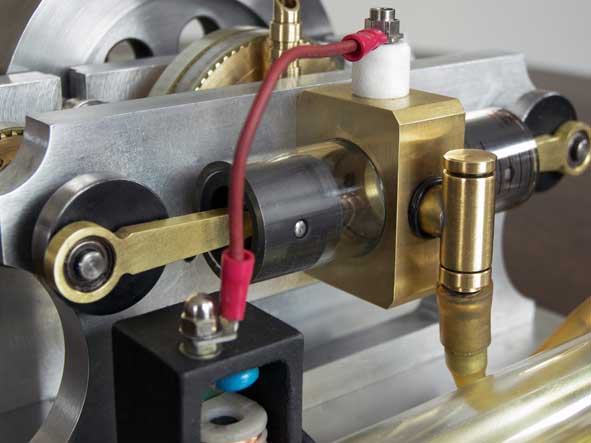
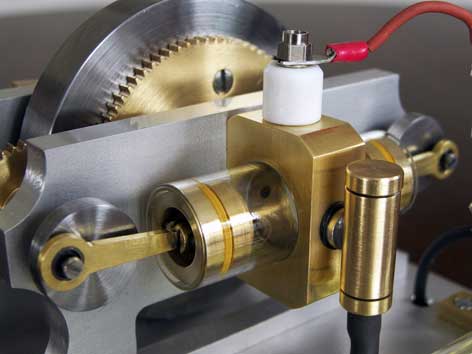
The spark ignition
The spark plug is only a Teflon isolator, directly screwed with fine thread in the brass central part of the cylinder combination; this to save space there and to be able to make the compression chamber small enough. The high tension electrode is soldered in a M3 thread end that is screwed in the isolator. This electrode is made from 0.6mm steel spring wire and is bend 90 degrees at the bottom of the isolator. The spark will occur between the electrode and the brass cylinder part that is connected to the mass of the engine. I did something like this before and it works very well. Of course I used the " Blokker mini circuit" as I did before successfully for some of my other models.
The spark is triggered by a reed contact that is switched by a Neodimium magnet in the start-up pulley on the fly wheel axle. This pulley is fixed on its axle so that the spark occurs exact at the moment that both pistons have made the maximum compression.The carburettor.
Because the whole design is about 30% smaller than the Ridders twin piston 4-stroke I had to make a smaller variant of the "Petrol Vapor Carburettor". I finally have chosen to make it from a glass tube, horizontally on the mounting plate to make the petrol surface as big as possible. I estimate that the engine will run for at least 10 minutes on that which is more than enough for a successful demonstration in my opinion. I am very satisfied with this rather cute solution if I may say so.3. Results
I really felt from my chair seeing for the first time very clear visible explosion fires when I faded out the lights in the workshop somewhat; see this video:
After about 10 runs of some 3 minutes the temperature of the cylinders and the brass central part appeared to be surprising low: not more than 40 to 50 degrees Celsius and with the wall thicknes of 1.75mm the glass seems to withstand the explosion pressure easily!
++++++++++++++++++++++++++++++++++++++++++++++++++++++++++++++++
B. The second (MK2) versionIntroduction
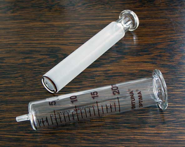
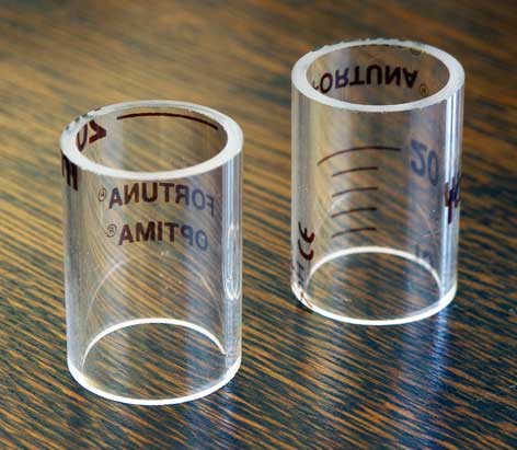
As said, the original plan to make graphite pistons without a rubber O-ring in perfectly round glass cylinders was in my mind all the time and it was a good friend who made that possible when he send me some glass syringes with inner diameter tolerance less than 0.01mm and 2mm wall thickness; exactly what I needed ! Another practical advantage is that these "Fortuna-Optima" syringes are for sale for some 10 Euro almost everywhere; for instance:
Poulten&Graf GmbH; see:
https://shop.poulten-graf.de/Spritzen/Ganzglas-Spritzen/
8.47 Euro excl BTW
Sigma Aldrich
20ml Z314366-10EA
glass Luer style; 10.50 Euro
http://www.sigmaaldrich.com/technical-service-home/product-catalog.htmlIn Belgium:
www.fiers.beThe concept of this MK2 version.
I figured out that is should be easy to convert my "Ridders 4-stroke engine" by replacing the cast iron cylinder/piston combination by this glass construction while the rest of the engine could stay intact.
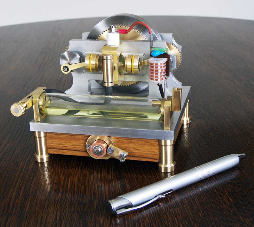
The CAD picture and photo below illustrate the design:
The inner diameter of the syringe glass is 19,59mm and I even cannot measure differences with my digital calliper meaning that the tolerance is less than 0.01 mm! The wall thickness is 2mm which is more than enough to withstand the combustion pressure according to my calculations and experience.
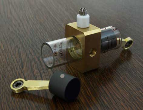
I could cut two cylinder out of one syringe and I made perfectly fitting graphite pistons in it with a clearance less than 0.01mm; see pictures below:
I made a brass fork that I glued in the graphite piston again with Loctite 603. After gluing I made the bore for the piston pin in one time through the piston with the fork. In this way the forces of the driving rod are on the brass fork and hardly or not on the weaker graphite
Alternative for the glass cylinders
If one can not obtain this special glass it is always possible to make the pistons from suitable steel or bronze with the same dimensions, but then the above mentioned optical benefits are lost. But the engine will not run less when the cylinder bores aer is made nicely smooth and cylindrical and well fitting pistons.
This MK2 version is about 30% bigger than the MK1 and runs very well, again showing the combustion fires if the room is darkened somewhat; see the video below:
+++++++++++++++++++++++++++++++++++++++++++++++++++++++++++++++++++++
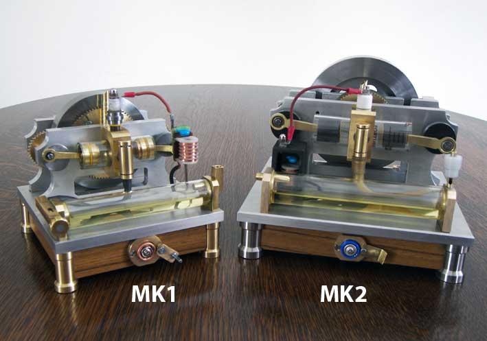
The MK1 version versus de MK2 version
The Mk2 version is the more perfect concept in the technical sense but the MK1 can be interesting as well especially for those who have problems obtaining the perfect glass an/or graphite and who are able to make gears themselves or buying them
Below a picture of both engines brotherly together.
For the MK1 as well as for the MK2 I made CAD drawing plans for what one can do an e-mail request to me.
MK1 version
Intake ball valve
Petrol vapor carburetor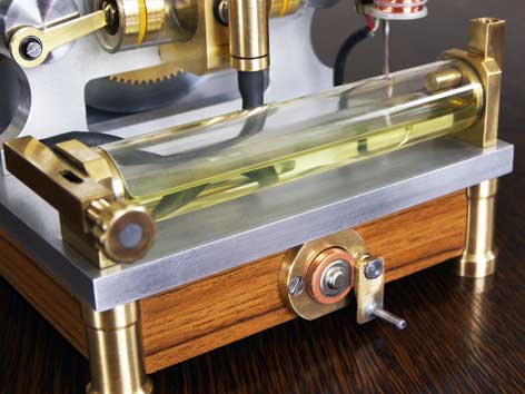
Reed schakelaar & magneet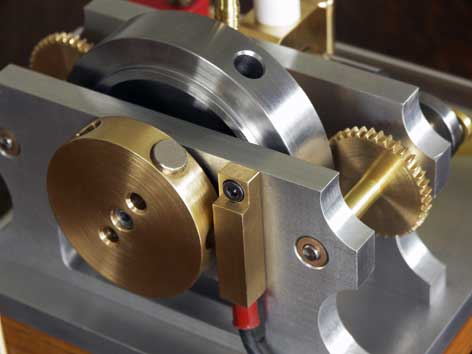
Very nice replica made by
made by
Bart van Duin
(cast iron cylinders):
MK2 version