Introduction
Earlier I made the "Linford 2-stroke engine" with two opposed pistons running in one and the same cylinder.
The gas intake, the exhaust and the spark plug are, as per definition, in the middle of the cylinder where the shared combustion chamber is situated. Making the intake and exhaust valves there, inclusive the rather complex driving systems with tumblers, pushers and cam discs as needed for 4-stroke engines is very difficult, not to say hardly impossible because the lack of space there. For me this was reason to make the "Linford opposed piston" a two stroke because 2-stroke engines don't have intake and exhaust valves at all.
During the last years I designed and used some simple sub constructions and "tricks" for my other IC engines. A kind of compilation of the most suitable "tricks" made it possible for me to design and make a 4-stroke opposed after all. Especially the very simple and compact rotary valve that I made for my "Ridders" 4-stroke engine" brought me the idea for this design. For further simplification I choose to let the engine be self sucking, using a small one way ball valve with what I have also good experiences.
The concept
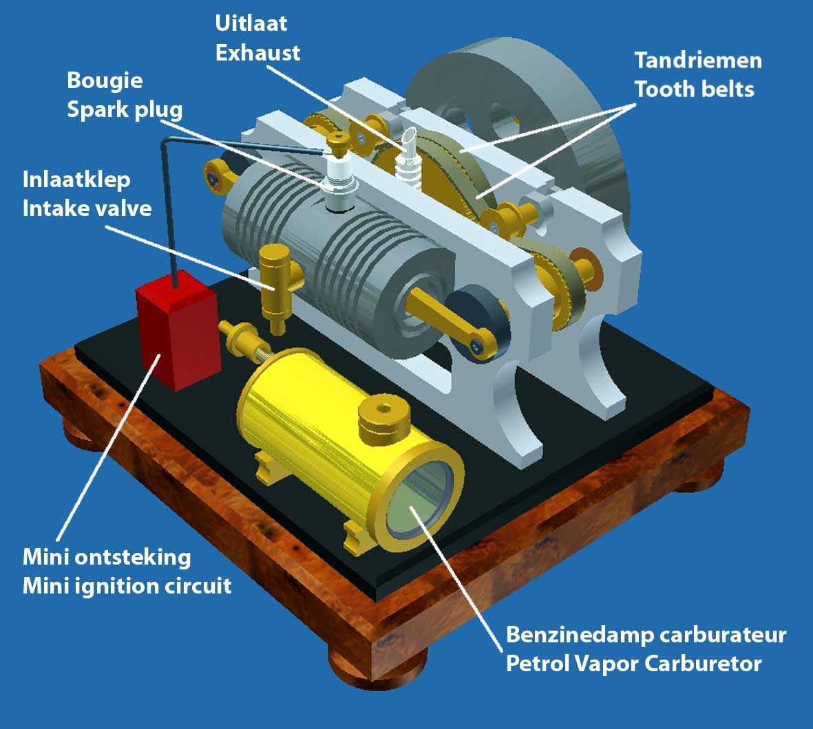
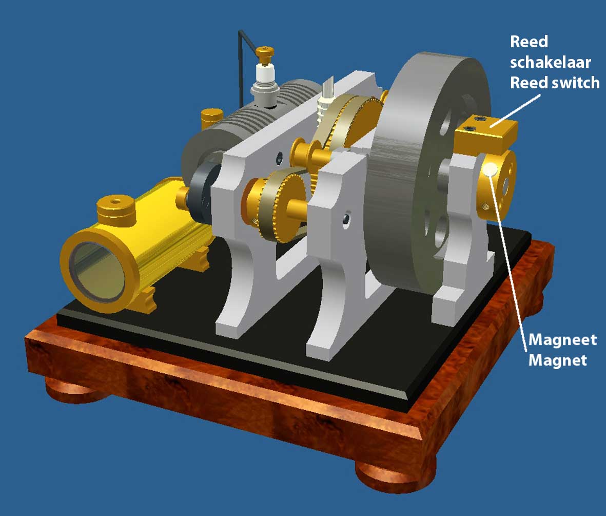
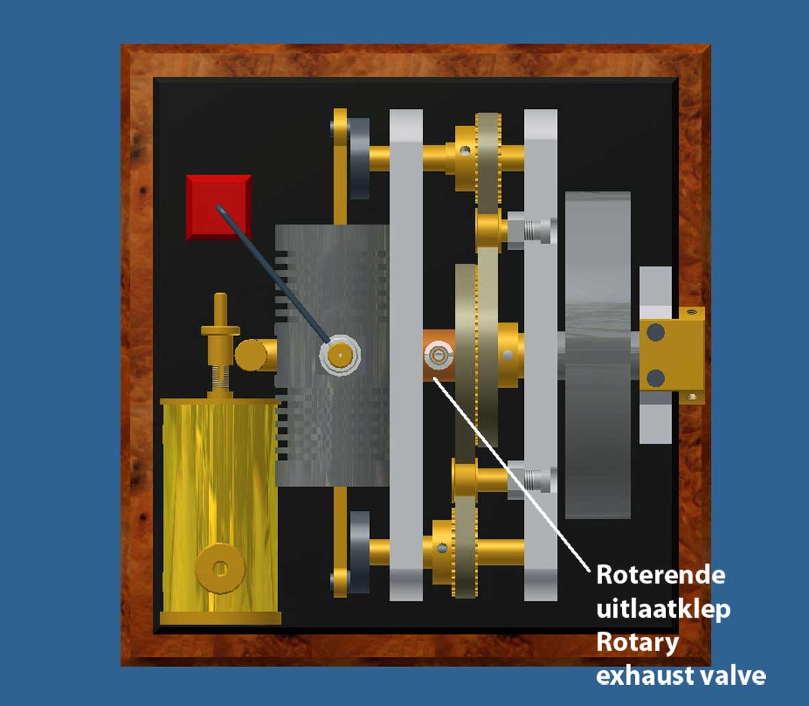
I finished the CAD drawing plan for this concept as per October-20-2011. The Cad pictures below illustrate the construction:
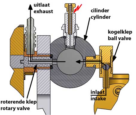
Cross section of the valve system
Some characteristics
1. I made the whole system horizontal to make the engine as compact and stable as possible.
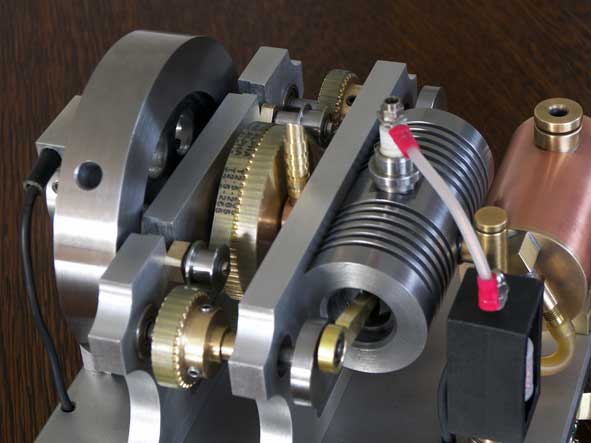
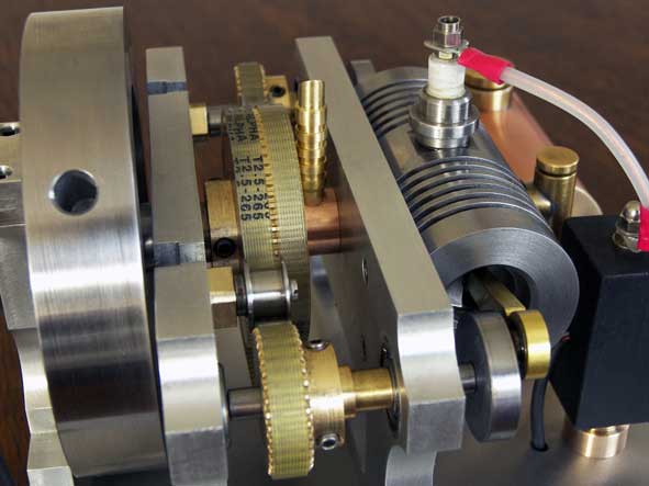
2. Again I used a tooth belt driving system for the reasons I earlier mentioned: great construction freedom, smooth and noiseless and no need for any lubrication. In principle it could be three gears running into each other, but in this case they would be rather big I think and they must be made dimension customized and for that I don't have the experience and tools.
It is of course possible to use one single tooth belt running over the 3 cog wheels, but making sufficient contacts over the wheel circumferences was rather difficult here. So I choose to apply two smaller tooth belts, one for the left and one for the right crank shaft, both running over the one central bigger cog wheel on the fly wheel axle. Therefore the width of this cog wheel is 2 times the width of the crank shaft wheels and the number of teeth is double to make a distribution 2 to 1 as is needed for every 4-stroke engine. Two stretching wheels are making the right circumferential stress and the rims on the wheels keep the belts in the right horizontal direction.
3. Although it is possible to make the rotary valve suitable for the intake as well as for the exhaust (as I did for the "Ridders" engine) I only use it here for the exhaust process because it makes the construction more compact and the creep age paths can be larger then, improving the air-tightness of the valve. In fact the intake can be self-sucking via a simple and small one-way ball valve. I have good experiences with such a valve that automatically opens itself when there is a partial vacuum during the intake stroke and closes also automatically during the other three strokes (compression, combustion and exhaust) during what an over-pressure occurs.
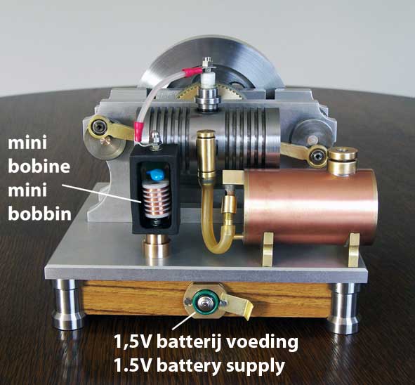
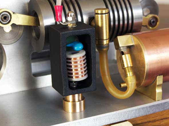
4. For the spark ignition I will use the very small gas lighter circuit that I developed recently, see the concerning page. I realize that not everybody will be in the position to make that, but most experienced model builders will have their own spark making solution I assume.
A compilation of suitable sub-constructions and "tricks"
This will be a compact and for all an unique and rather easy-to-make 4-stroke opposed piston engine if I may say so. Sort of combining suitable design "tricks" that I implemented earlier for several other of my other IC models, as there are:
- Two opposed pistons running in one and the same cylinder with a shared combustion chamber in the middle of the cylinder. One of the advantages is the fact that with that there are no cylinder heads. May be not more efficient (I have no idea) but at least it compact and funny to see;
- Very easy mechanisms for the intake and exhaust processes, respectively with a one-way ball valve and a simple rotary valve. The process adjustment is very easy and only concerns the positioning of the mandrel in the rotary valve on the fly wheel axle;
- Simple external crank shafts with ditto driving rods without crank case;
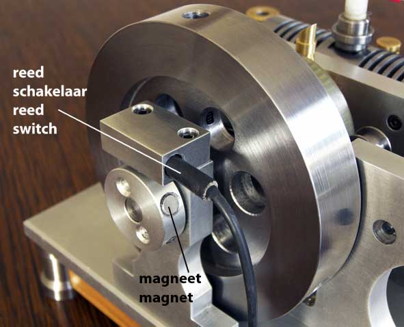
- Super small and own made ignition circuit for the spark on a self made spark plug. A small Neodymium magnet in the start-up pulley triggers a very fast reacting reed switch for the spark on the right moment in the process. The current through the reed switch is so low that the life time will by almost "eternal" I think. The single spark ignites the gas mix above both pistons at the same time so there is no need for a spark distributor or a double bobbin system;
- No systems for forced cooling and lubrication mainly as a result of applying grey pearlitic cast iron for the cylinder and pistons. If the pistons are made nicely fit in the cylinder there is no need for piston rings. Not only easier but it also reduces the piston frictions to a high extend;
- Applying the trouble free "Vapor Carburetor".
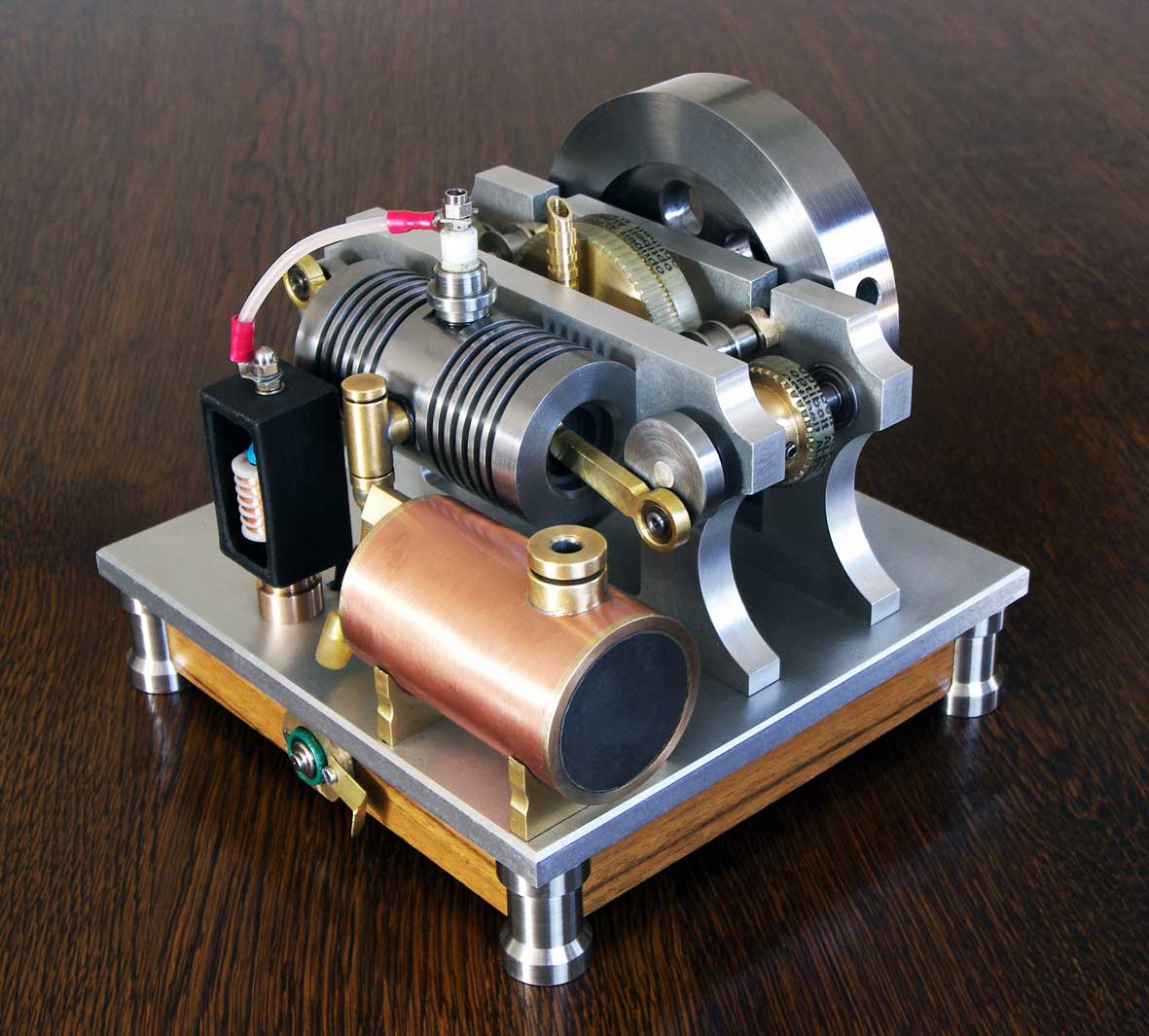
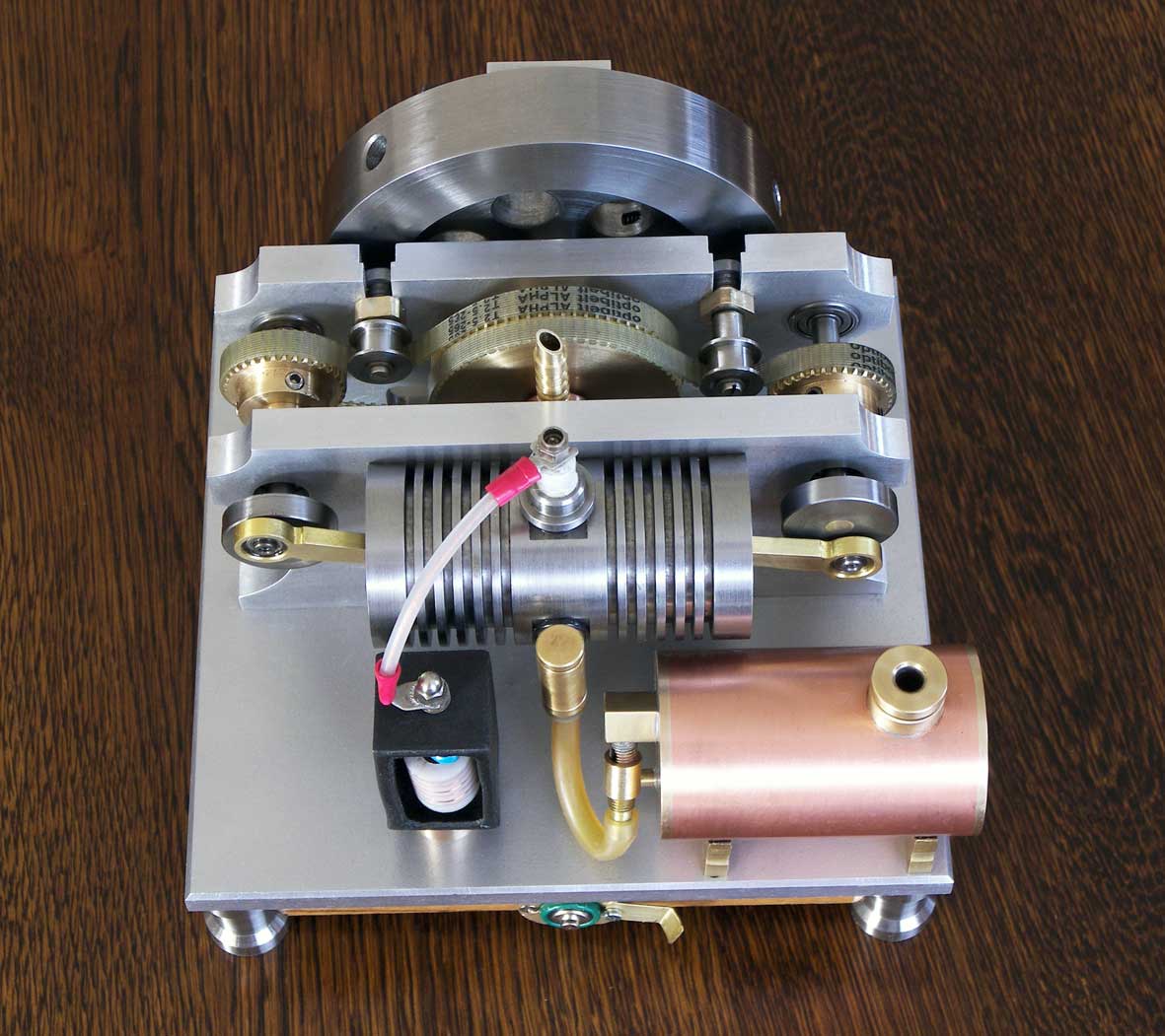
The result
The engine is running perfectly with adjustable speed between 600 and 1100 RPM; see the video below:
The drawing plan is available for everyone interested.