The idea
Coffee cup Stirlings are well know models and you can find them anywhere on Internet. But except for pictures, some stories and building kits I could not found any suitable drawing plan. But that doesn't matter for me, because I always like to build from scratch based on own designs and taking my machinery and material opportunities into account.
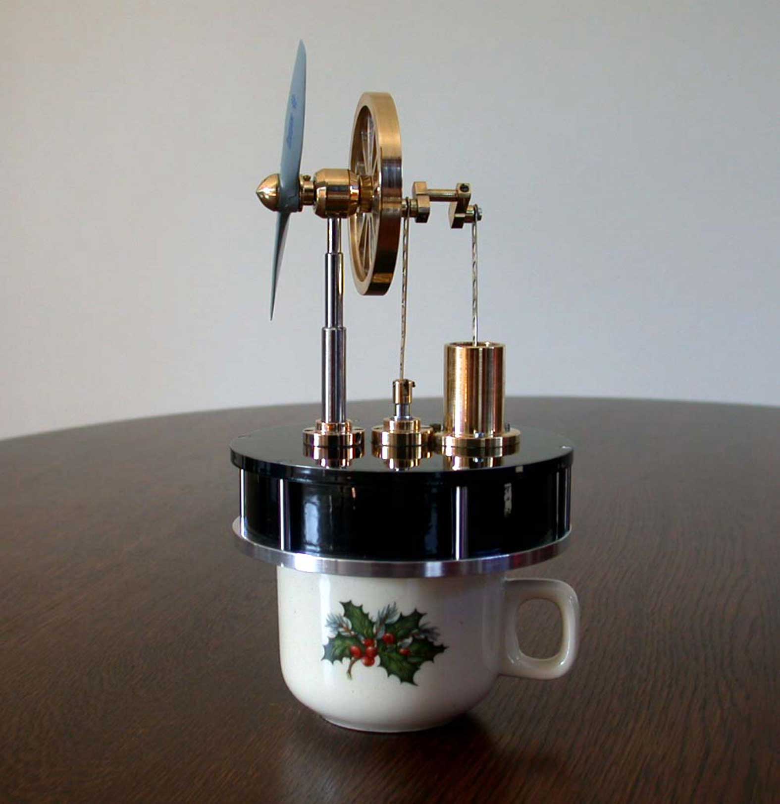
The Coffee Cup Stirling is a very simple engine but surely not inferior at all. On the contrary, it is one of the best "instruments" to demonstrate the Stirling principle. You only need a cup with hot coffee or water to let it run; no flames, no steam, no explosions, no smell, no noise, no danger. The only engine you can demonstrate while drinking coffee with your friends in your living room. Success always guaranteed even for non technical orientated spectators. And even with some fantasy and good will you can give it an eye-catching appearance and let them look like a small ornament.
Vido:
Characterization and working principle
Typical for this Stirling model is the relative big surface of the air displacer. The reason for that is the rather low working temperature; less then 100°C.
There is a certain optimal relation between the diameter of the displacer and that of the working piston. The volume of the air in the system is alternating due to the temperature differences, at least when you have a moving working piston, which is the case here. The volume displacement of the working piston is fixed due to the mechanical dimensions (stroke x piston surface). This volume must be equal or less than the volume differences due to the alternating temperatures of the air. If the volume displacement of the working piston is bigger then that it will counteract the movement at some time in the cycle. So, the relation between the diameters is a function of the air temperatures, the total volume in the system and the stroke of the working piston. You can measure the the temperature of the lower plate, but it is difficult (or hardly impossible) to measure the dynamic and alternating air temperatures in the system. I empirically determined that in this case the diameter of the working piston must be at least 7 to 8 times smaller then the diameter of the displacer, resulting in a diameter of 13mm for the working piston and 96mm for the displacer cylinder.
Also typical is the fact that the displacer cylinder and the displacer are made out of plastic. Because of the low heat lead of this material the temperature difference between the upper and the lower cylinder plates can be made and maintained as high as possible.
If the engine is placed on a cup with boiled water the temperature of the lower plate will rise to about 80°C within a minute or so. The air in the displacer room expands, pushing the working piston upwards. If the displacer is moving downwards again the air is driven to the cold room above the displacer along the small space (about 1mm) between the displacer and the cylinder wall. The relative cold upper plate is cooling the air and, as a result, the working piston is pushed down again due to the overpressure of the outer atmosphere. This is the basic principle of a Stirling engine.
The connecting rods of the displacer and the working piston are coupled to each other on the crank shaft so that the phase shift between them is 90° within the cycle. So, if the working piston is at his upper and/or lowest position the displacer is halfway its stroke and vise versa.
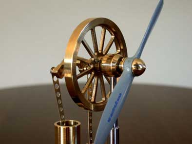
A fly wheel on the crank shaft helps the movement through the dead points causing the cycle to repeat as long as sufficient heat is supplied to the lower plate.
The maximum permitted temperature of the plastic parts is limited but will not be exceeded on a cup with boiling water.The elaboration
Preferably use clear plastic for the cylinder wall so you can look into the engine, seeing the displacer movements and the open connection to the cylinder for the working piston. You can cut it out from some packing material like a biscuit box that you can buy in any warehouse (at least in Holland). Clear plastic tubes are made with all kinds of diameters and wall thicknesses but it is not always easy to find a supplier for that. If you cannot obtain this material you can use the well known opaque PVC drain tube but then you miss the nice look-in.
The cylinder wall fits into grooves in both aluminum plates. Rubber rings in the grooves make the connections air-tight when the plates are mounted to each other with the 6 fixing spacers on the circumference. You can make such a ring by cutting the right length from a silicone rubber hose (f.i. used as fuel hose for model air planes), laying it in the groove and putting some few silicone glue to the cutting faces.
As an alternative you can cement the cylinder wall into the grooves with a suitable (silicone) glue. The advantage is that you need less parts and you eliminate heat lead from lower plate to upper plate through the 6 metal fixing spacers. The disadvantage is that dismantling the engine (if necessary) is less easy.
The displacer must be light, more or less heat isolating and, for all, flat to avoid touching the cylinder plates. I used 4mm thick polystyrene (foam plastic). May be balsa wood (as used for model air planes) is a good and/or better alternative because it used to be more rigid and flat.
Never oil the working piston in the cylinder!! Even very thin oil is more or less viceus and increases the friction. Mind that the power of this type of Stirling models is very low so little friction can be fatal.
The working piston can be made from graphite or steel. Graphite is more or less self greasing and the friction in the cylinder is and stays always low. A piston made from steel can work very well too if it is made accurate and with a smooth surface. But it is my experience that steel pistons need somewhat more maintenance in the sense that they must be cleaned and or polished from time to time to keep the engine's performance optimal.
The propeller is a cosmetic feature here; the cooling effect on the upper plate is negligible. I used a propeller for model air planes (brand Graupner; wing span 120mm).
Most remaining parts are made out of brass as you can see on the drawing plan.Minimizing friction and balancing the mechanical system
There are two counter forces that this low power engine must conquer to keep it running:
1. Mechanical frictions.
You cannot eliminate frictions for 100%. The one who said he can has invented the perpetual motion.
My hints to make the lowest possible friction are:
- Use good quality ball bearings on the fly wheel axis, wash them in dry-cleaning naphta and don't oil them;
-Use standard material for the displacer axis and the glide bearing for it; don't oil;
-In case of a steel piston: polish the somewhat oversized piston in the cylinder with fine polishing paste and clean everything thoroughly. The combination is perfect if the piston stays on place in the cylinder while your thumb is closing the cylinder bottom (=sufficient air-tightness) and falls down by its own weight when you remove your thumb (=low friction). Don't oil!
-Take care for a good alignment of all moving parts;
-The displacer may not touch anything in its cylinder. If necessary reduce the displacer diameter a little; the space between the displacer and the inner cylinder wall is not that critical;
You better accept (very) small air leakages other than too high frictions!2. Gravity force on the asymmetrical mechanical system.
You can eliminate the gravity counter forces on the asymmetric system for almost 100% with balancing. It improves the performance of the engine significantly.
Balancing must be done with complete assembly but with removed lower plate to avoid air-pressure influences:
-Mark the relative position of the flywheel to its crank axis;
-Push the fly wheel, wait till the rotation stops and mark the top side of the fly wheel;
-Fix a small metal part (f.i. a nut) there and experiment with the weight of that part until the fly wheel stops at random places;
-Calculate the amount of material that you must drill out on the opposite side of the fly wheel, based on the weight of the final test weight;
-Drill the holes with somewhat smaller diameters then calculated and gradually enlarge them until the flywheel stops at random places.
-Take care that you mount the fly wheel every time (and always later) according to the markes on the wheel and the crank axis.
Of course you also can choose to add a weight to the opposite side of the fly wheel in stead of drilling holes ; it is a matter of taste.
The performance of the engine
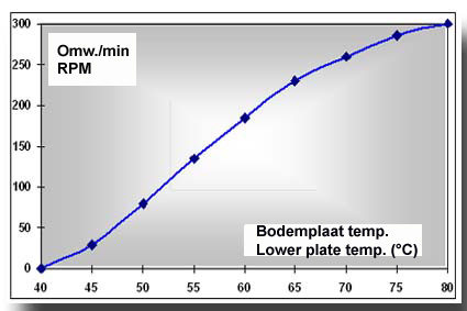
Placed on a coffee cup with boiling water you can start the engine by pushing the fly wheel after about half a minute in the right direction. After 1 or 2 minutes the maximum revolution speed of about 300rpm is reached. I measured the revolution speed as a function of the lower plate temperature; see graph below.
The running time depends on the cooling speed of the water in the cup.
On a not isolated coffee cup the engine will run for about 25 minutes; on a thermos bottle your can reach run times up to one hour or more. The engine will run continuously on any device that keeps the lower plate temperature between 50 and 100°C, but don't exceed this 100°C too much to avoid damage to the plastic parts.
Checks in case of troubles
In case the engine runs bad or not at all perform the following checks:Friction:
- The unloaded fly wheel must rotate for at least 4 minutes after you gave it a firm push by hand;
- With only the displacer coupled to the fly wheel this rotating time must be at least 15 seconds;
- With coupled displacer and working piston this rotating time must be between 5 and 10 seconds (10 to 20 strokes).
Air leakages:
- Remove the working piston and connect the work cylinder with some kind of rubber stop to a low pressure device (max 0.5 ato);
- Immerge the engine to halfway the working cylinder in water and check for air bubbles.
You almost always will see some leakage along the displacer axis, but if this is not more than some 1 to 5 tiny bubbles per second there is no problem.
Any other leakage in the stationary system must be eliminated. You can seal the work cylinder to the upper plate with a thin film of silicone kit.
Of course in this way you cannot test the air-tightness of the working piston in its cylinder, but the "thumb" test as described above is sufficient.Final test:
Uncouple the connecting rod for the working piston from the crank shaft. Put the engine on a cup with hot water and wait till the lower plate is so hot that you cannot stand touching it by hand (more than 60°C). Turn the fly wheel and check if the (free) piston is moving up and down after you have put it halfway the cylinder. You must feel any up and down force with the connecting rod between your fingers and rotating the fly wheel.
Remark:
The model as shown in the pictures and the video clip differs somewhat from the drawing plan. I recently made a new CAD drawing plan for this Coffee Cup Stirling, implementing some improvements at the same time, based on my experiences with the Low Temp Stirling. This plan is available for every one interested; click here for a request.
Nice replica made by Txema Egizabal:
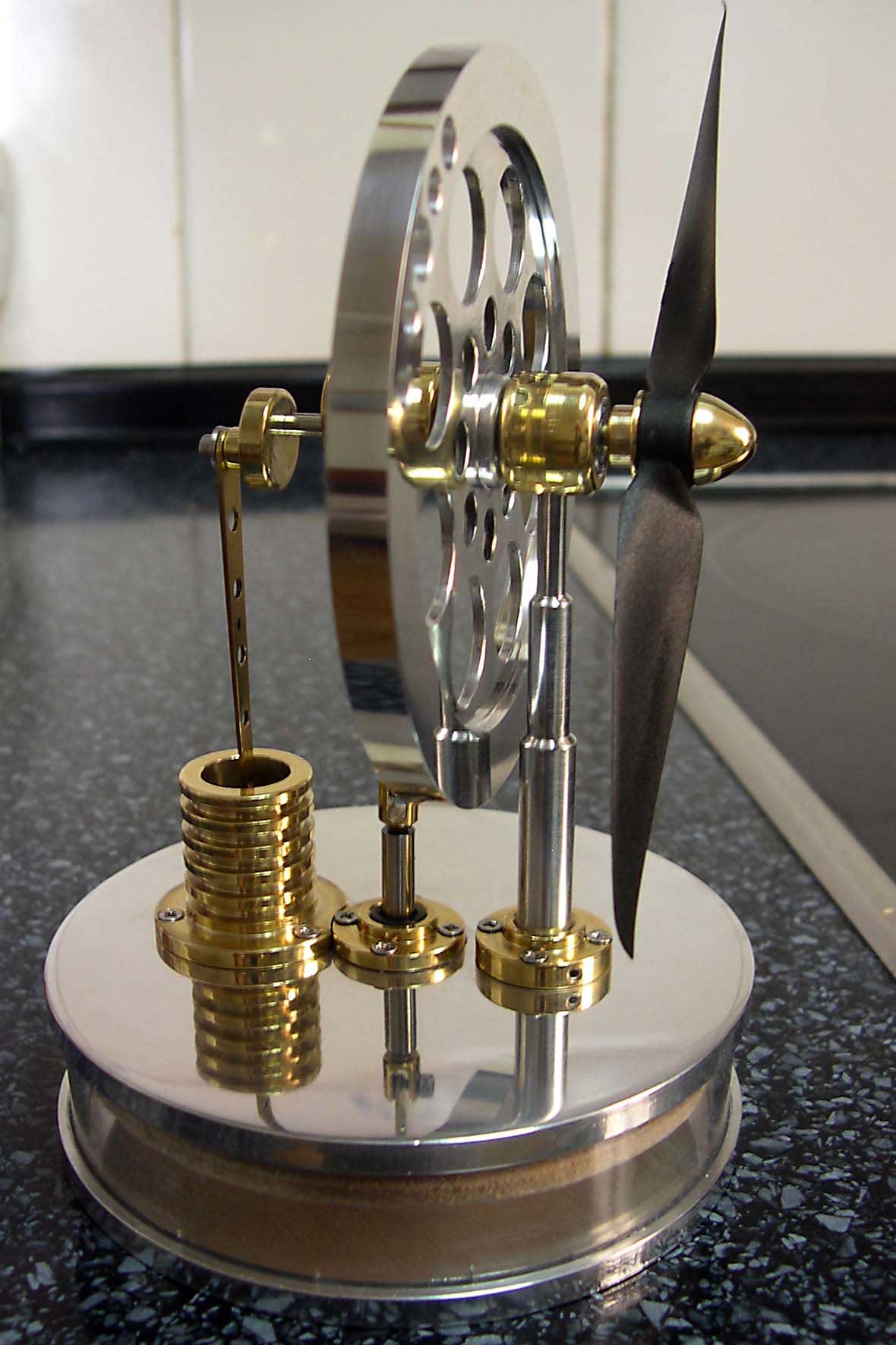
Nice replica made by Antonio Fattore: