Introduction
My experiences with glass cylinders and graphite pistons with IC engines (see eg 1-Cylinder 4-stroke, the 2-cylinder 4-stroke and the Hybrid 2- / 4-stroke) brought me the idea to make a design for a flame-eater with a glass cylinder . Not only because it is unique and exciting to glimpse into the cylinder, but also to deal once and for all with the eternal evil of all flame-eaters, namely corrosion of the cylinder and the piston caused by the hot and wet sucked-in flame gases. The result is increasing of the friction between the piston and the cylinder and, with that, gradually slowing down the speed of the engine ending with a final stop. Regular dismantling and cleaning therefore is common for almost all flame-eaters.
Glass and graphite don't corrode under these circumstances and the self-lubricating graphite piston remains running practically frictionless in a glass cylinder without any lubrication and cleaning maintenance. And this self-lubricating property of graphite is an important advantage because oil lubrication is not possible with flame-eaters because oil burns quickly leaving residues behind with fatal friction as a result.
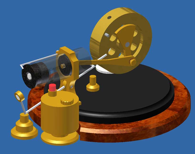
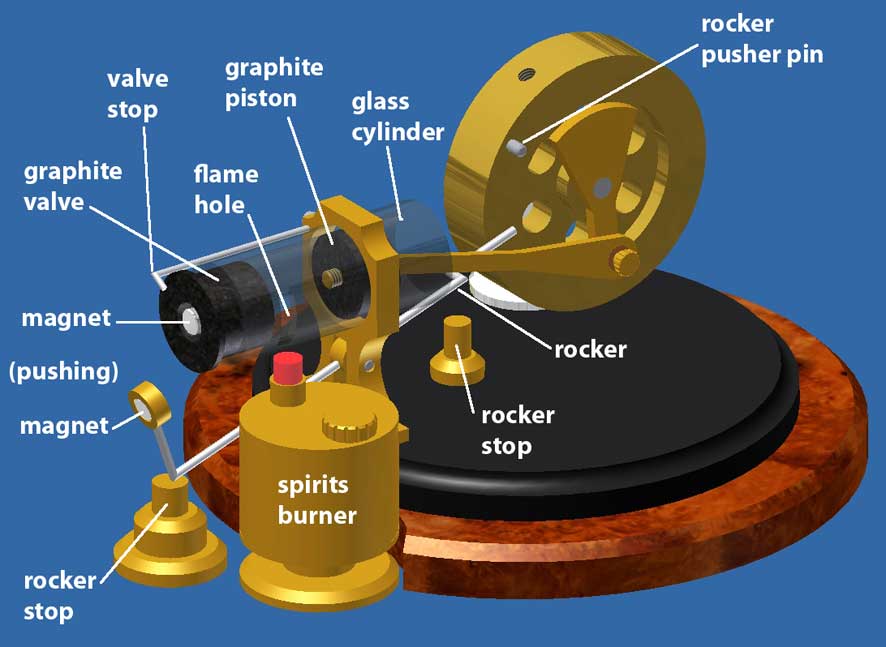
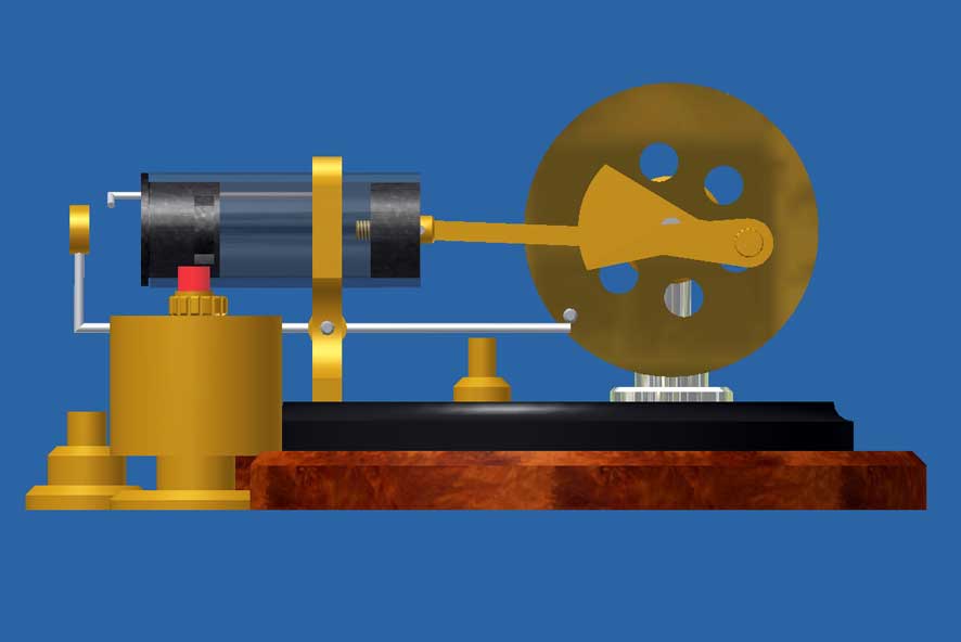
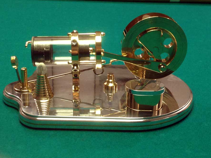
The figure below shows the CAD design of this flame-eater:
This design is derived from my earlier 1-cylinder flame-eater with an internal valve as I made before, see for the operation principle and the special features the concerning page.
Except the fact that the cylinder is made from glass the control of the internal valve is quite different here. I glued a small Neodymium magnet with Loctite 603 in the centre of this graphite valve. A similar magnet is mounted on a tumbler that is operated by a pin on the flywheel in such a way that both magnets are facing each other for a short time at the moment the piston has reached its TDP (Top Dead Position). The inter-field direction of the magnets is selected so that they repel each other so that the valve is pushed over the flame hole in the cylinder wall. At that moment, the pin on the flywheel leaves the tumbler and the magnet falls back in its lowermost position. The exact adjustment of this movement is simply a matter of securing the fly wheel in his correct position on the crankshaft. Because the cooled-down flame gases create a partial vacuum in the cylinder the piston is pushed back by the outside atmosphere in the direction of the flame hole that remains closed as long as there is a partial vacuum in the cylinder. As soon as the flame gases are compressed to normal atmospheric pressure by the piston displacement (just somewhat before the piston arrives at the flame hole) the internal valve will be automatically pushed back until it just opens the flame hole somewhat so that no counter-acting over pressure in the cylinder will be relieved. That means that this internal valve also acts as a pressure relief valve. When the piston passes through as a result of the flywheel effect a cam on the piston taps against the valve so that the flame hole is opened fully. The valve is captured by an adjustable stop in order to prevent the valve flying out of the cylinder. When the piston returns its direction by the flywheel effect new flame gases are being sucked into the cylinder through the open flame hole until the valve is pushed over it again and the process repeats itself.
The elaboration of the concept
1. The glass cylinder
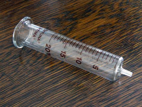
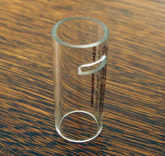
As I did before with some of my little IC engines I cut the cylinder from the barrel of the a glass syringe "Fortuna Optima 20ml"; manufactured by Poulten&Graf, Germany, see pictured above. The tolerance of the inner diameter thereof is extremely small (+ / - 0,01 mm!), necessary to make a virtually leak-free graphite piston in it. The glass is also very heat resistant so it does not burst by heating it with the alcohol flame in front of the flame hole.
I could by chance obtain some of these glass syringes from a fellow model builder so that I myself have as yet not bought some from a supplier for which I mention a few below:Poulten&Graf GmbH with busuness establishments in Duitsland en Engeland
https://shop.poulten-graf.de/Spritzen/Ganzglas-Spritzen/
Art. nr. 710241; 8.47 Euro excl BTW
Sigma Aldrich
20ml Z314366-10EA
glass Luer style; 10.50 Euro
http://www.sigmaaldrich.com/technical-service-home/product-catalog.htmlIn Belgium
www.fiers.be
Art. nr: C681.1The inner diameter is 19.60 mm with an extreme small tolerance of 0.01mm or even less; the wall thickness is 2mm.
I cannot remove the marking on the syringe cylinder; a little bit pity, but not that bad because one can look very well inside despite that.2. Cutting the cylinder and making the flame hole in it.
Cutting the glass nicely square and especially making the flame hole in the cylinder wall is a more or less a special job. Due to the relatively thick wall (2mm) this only can be done well with a thin diamond grinding disc in a high speed grinding tool like Dremel. For this kind of work I myself made a special but simple arrangement which what this can be done easily and well, see the concerning page on this website.
To my pleasant surprise the mechanical strength of the glass at the location of the flame hole appeared not to be affected by the grinding. More important in this case was that it survived easily the heat of a spirits flame and this is of course a precondition for applying a glass cylinder for a flame-eater.3. Fixing the cylinder in the support.
The cylinder is glued in the brass support and I did this as follows:
- Global fixation with some small dots of plumbers silicone sealant in the about 0.5 mm oversized hole of the support. Because this sealant is hardening slowly there is plenty of time to put the cylinder exactly on the right place and nicely horizontal, supporting the cylinder with some small cubes left and right from the brass support;
- After some few hours, this silicone sealant is hardened so that the cylinder is fixed sufficiently strong to fill the remaining spaces with little Loctite 603. Twenty-four hours later, the connection of the cylinder in the brass support is very strong. The only force that is exerted on this connection is caused by the friction between the graphite piston and the glass and that is, as said, very low.The magnet system
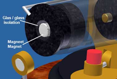
1. The magnets and the temperature thereof
In the graphite valve as well as in the head of the rocker arm I glued a little Neodymium magnet with Loctite 603. You can sell these kind of magnets with 6mm diameter and width everywhere on internet for some dimes.
Beyond about 80 degrees Celsius the magnetism of these magnets is lost wholly or partially, and that was more or less the case when I let the engine run for some time. Graphite has a relatively high thermal conductivity (160 W / mK) and that was apparently the reason why the temperature of the magnet just exceeded 80 degrees Celsius. I solved this problem by gluing a closed top of a small glass test tube in the graphite valve in what I glued the magnet; see the picture on the right of this page. Because the thermal conduction of glass is very low (0.9 W / mK) the magnet temperature now keeps below the maximum allowed 80 degrees Celsius.2. The tumbler system
Initially I had problems with this system because the rotation direction of the whole system continuously and suddenly reversed causing the engine to crash against the pin in the flywheel that drives the tumbler. After a lot of investigations and experiments I found out that this was the result of floating and/or bouncing of the rocker arm and sometimes by shooting the magnet above the magnet in the valve. This disrupted the valve movements and thus the timing of the process. I have solved this problem by limiting the stroke of the rocker in both directions with two metal stops on each side of the rocker. From that moment the flame eater runs perfectly and continuously and without any pollution.
The adjustment of this flame eater is only a matter of securing the flywheel to the crankshaft in such a way that the valve is pushed over the flame hole at the time that the back side of the piston is approximately 5.5 mm away from its utmost position. The adjustable stop for the valve slide must be fixed so that the valve just completely opens the flame hole.The result
During the first 15 seconds there will be some water condensation of the flame gasses in the cylinder that you can see through the glass cylinder. But once the water condense has disappeared due to the temperature rise the engine runs 100% reliable, with a very constant and "genteel" speed of 250 revolutions per minute. This speed is probably mainly determined by the various mass moments of inertia in the system.
The movements of the piston and the valve are obviously and clearly visible through the transparent cylinder which is not only nice to see but also useful during the one-off adjustment of the process timing.
So I have reached my main objective, namely that any maintenance of regular cleaning is completely eliminated, a unique feature for a flame eater that none of my previous flame eater have.
Finally
I have made a CAD drawing plan that is available for anyone interested, click here for a request.
The design is basically very simple, but getting some special materials such as the "Fortuna Optima" glass syringe and the graphite shows often to be an obstacle in the sense that you cannot sell it on every corner of the street. The relatively very cheap Neodymium magnets are widely available, so that will be no problem.
Also, the cutting of the glass, and for all making the flame hole therein is not really daily work. In itself not difficult, but I myself had to make a special arrangement for it with what I am very happy because I can do all this kind of glass treatments with it easily.
A brilliant replica made by
Tiny van den Boom:
Nice replica made by Antonio Fattore: