Flame eater with external valve principle
In fact the flame-eater principle is very simple. Hot gasses from a spirits flame are sucked in the cylinder through a hole when the piston moves away from that hole. If the piston arrives at its most left position (see the animation below) a valve closes the cylinder hole so the hot gasses are trapped. From that moment these gasses cool down against the cylinder wall causing a partial vacuum in the cylinder. The pressure difference with the outer atmosphere causes a force on the cylinder to the right so it will move back in the direction of the cylinder hole. This piston stroke delivers the power of the engine. Just before the piston is reaching its most right position the valve opens the cylinder hole again causing the cooled and suppressed gasses to be pushed out of the cylinder. Due to the fly wheel effect the engine will remain rotating so the piston will move again in the other direction repeating the process cycle. The animation below demonstrates this process for a classic flame-eater with external valve.
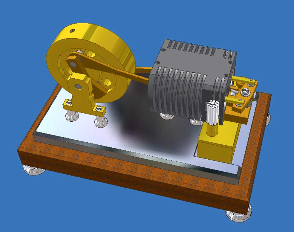
The classic construction for a flame-eater with external valve
The pressure difference over the piston is rather small and can never be more than 1 atmosphere per definition. This should be the case if there should occur an absolute vacuum in the cylinder, but in practice that won't happen. The pressure difference will not be much more than some tenths of an atmosphere. That is the reason for the low power of every flame-eater. So, one mustn't expect a flame-eater to be able driving something more significant than its own mechanism. As far as I know there are no other applications for these engines than nice modelling objects which are relatively easy to build.The idea for this 2-cylinder flame-eater with internal valves
The valve of classic flame-eater designs is always on the outside of the cylinder and it is pressed against the cylinder surface with some kind of spring construction. The valve is coupled on a driving rod that is moving over a cam disk on the fly wheel axis. The cam profile must be made such that the valve is closing and opening the cylinder hole on the exact moments in the cycle. I used this construction for three of my former flame-eaters: the "Flame-eater Marc"; the "Two cylinder flame-eater" and the "Miniature Flame-eater".
This valve mechanism is rather complex compared to the rest of the engine, but in particular the adjustment of the whole system is very critical most of the time. Already small adjustment deviations can cause a bad or not running engine. Although my former flame-eater are running well the adjusting problems I encountered brought me to the idea to develop a system where the valve is closing and opening the cylinder hole from the inside in stead of on the outside. This internal valve is a second cylinder which makes a small stroke only over the inside hole area. This construction makes it possible to drive this valve directly by the piston in a very simple way without any driving rod and cam disk.
Earlier I made a 1-cylinder flame-eater with internal valve with the same principle which is running very well if some pre-conditions are fulfilled which you can find on "Trouble shoot check list" on the page for that engine. These conditions are rather stringent as a consequence of the low power of the engine. Furthermore, a 1-cylinder is powerless during half the cycle when the piston is sucking in the flame gasses. During that stroke the engine must be kept running by the rotation energy that is stored before in the fly wheel.
According to my experiences a 2-cylinder flame-eater is much less sensitive for disturbing elements in the system. Not surprising of course if one realizes that the one piston provides power when the other piston is powerless and vice verse, under condition that the pistons are shifted 180° to each other in the movement diagram. This brought me the idea to design a 2-cylinder version of a flame-eater with internal valves.
The working principle of this 2-cylinder design with internal valves
It was my choice to accommodate the two pistons in one cylinder block. Except for the fact that this makes the engine compact it makes it also possible to drive the valves with an exceptional and supreme simple construction making use of the fact that the pistons are shifted 180° to each other. The animation above shows how the one valve pushes the other one over its flame hole and vice verse with the help of a tumbler system. With this design the timing of the process is completely and implicit determined by the dimensions of the engine.
In the animation the sucked-in flame gasses are coloured red while the cooled gasses that bring the engine's power are coloured blue.
If the pistons are moving to the left during the power strokes the cooled and low pressure gasses are suppressed again. The normal outer pressure is reached already some time before the piston has completed its power stroke. If the valve should keep the cylinder hole closed during the last part of the power stroke an over pressure will occur that will slow down the engine significantly. This is a well known phenomenon for all flame-eaters. With this design I make a provision that automatically prevents an over pressure in the cylinder; see the description of the tumbler construction below. If one looks well at the animation this effect is visible there: the valve is pushed back just before the piston has finished its power stroke.
Caused by the fly wheel effect the piston finishes its stroke and a cam on the piston pushes the valve in its most left position, opening the hole completely to clear the way for the flame gasses to be sucked-in again when the piston moves to the right again. At the same time the valve in the other cylinder bore is pushed over the flame hole by means of the tumbler so the sucked-in flame gasses there are trapped between the valve and the piston that is just arrived in its most right position.Video:
The elaboration of the engine
1. The pistons and the valves.
The pistons and the valves must run very smoothly in the cylinder but on the other hand they must fit almost air-tight in the cylinder without any oil. Therefore the bores in the cylinder must be smooth and exactly cylindrical; the absolute cylinder bore diameter is not important at all because you first must make these bores and after that the pistons and valves so that they fit nicely in the bores with the smallest possible clearance.
In all cases the diameter differences over the bore length must not be more than 0.02mm to realize a final piston/valve clearance of about 0,03mm maximum. The best way to do that is honing, but most model builders (like me) don’t have the equipment for that. A good alternative is reaming the bores as a last treatment. I reamed the cylinder bores manually with an adjustable reamer and with ample oil, turning around the cylinder several times with the same reamer adjustment until the reamer passes easily through the bore. Then adjust the reamer a fraction wider and repeat this treatment again and again until you cannot measure hardly any diameter difference over the cylinder lengths any more, at least less than 0.02mm. This way of working can compete with real honing and is a good alternative if you don't have honing equipment.
- In case you use pearlitic grey cast iron for the cylinder, pistons and valves:
After you made the cylinder bore as described above lathe the pistons and valves exactly cylindrical and smooth until they fit somewhat "sticky" in the cylinder bore. Then grind the pistons and valves in the cylinder manually with very fine grinding compound until they can slide nicely through the cylinder bore. The clearance will be less then 0.03mm which causes sufficient air tightness.
The only disadvantage of grey cast iron is that it is rust sensitive due to the hot and wet flame gasses resulting in increasing and finally fatal friction. Therefore you must clean the cylinder, pistons and valves regularly, at least before storing the engine for a longer time.
- Graphite for the pistons and valves is the best you can use if you can obtain it in small quantity and for a reasonable price. Graphite is self greasing and not corrosive so with that the engine is running better, more reliable without hardly any maintenance and you can use all kinds of other material for the cylinder like bronze or rust free steel. You can make the graphite pistons/valves fit well in the cylinder bores as follows:
Lath the graphite pistons and valves inclusive the chambers (in what the brass forks are situated) with a somewhat oversized diameter. Make a cylindrical metal mandrel with such a diameter at one end that the chamber of the piston/valve can be put somewhat clamping over that part of the mandrel. Clamp the mandrel in the chuck of your lathe with the turning center against the piston/valve and turn the diameter back in small steps until they fit well in the cylinder bore. With some care and patience it is well possible to make a clearance of about 0,03mm (or even better).
Checking the low system frictions with a cold engine without any oil and no flames(see also the demo’s on the video):
- Remove the two valves;
- Push the fly wheel firmly manually; the pistons must run for 8 to 10 seconds in the cylinder bores;
- Mount the tumbler system with the two valves in the cylinder bores;
- Push the fly wheel firmly manually; the whole system must make about 10 strokes.
Checking the air-tightness of the pistons and the internal valves with a cold engine without any oil and no flames:
- Turn the fly wheel until one piston is in the utmost right position;
- Push the internal valve in the utmost right position also whereby the cylinder hole will be closed;
- Move the piston slowly to the left by rotating the flywheel. As a result the overpressure that occurs immediately in the (cold) cylinder will push the internal valve to the left until it just opens the hole in the cylinder. If the piston is moved further to the left the valve will not move anymore because the overpressure has disappeared.
- Repeat the same test for the other piston and valve.
If the valve doesn't move at this test there is a too great leakage along the piston and/or the valve. Then the only remedy left is to make a new piston and/or valve””
2.The tumbler construction
See assembly above and the pictures 3 and 4 on the right of this page.
In the tumbler that can move around on a vertical axis there are two little ball bearings with the same pitch as the cylinder bores. In the horizontal axes of the valves there are vertical draggers (pins) that insert these bearings. On picture 4 one can clearly see that these pins with diameter 2mm have a 1mm clearance in the 3mm ball bearings.
This 1mm clearance has a dual function:
1. The ball bearings move with a small arc of circle. Without any clearance the system would be wrenching because the valve axes are screwed-in. I could have made pivot points there but except from the fact that the construction would be more complex I needed this clearance for another and a more important reason:
2. As said above an over pressure in the cylinder must be avoided. The 1mm free stroke that the draggers have in the ball bearings is just enough to enable the slightest over pressure to push the valves back automatically. Because the valve overlap in its closing position is a fraction less than 1mm this backstroke causes a small leakage, just enough to eliminate the over pressure. In fact the valves also have a pressure relief function. If one looks well you can see this typical effect on the animation above.
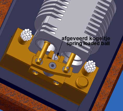
However the tumbler construction appeared to have an unforeseen property that was fatal without a special facility. The tumbler movement was extremely indeterminate with the result that the system starts floating due to the intense blows of the pistons. The tumbler was leading its own life so to say with the result that the timing for closing and opening the cylinder holes was seriously disturbed. The engine refused to run or at the best very short, restless and stuttering. It was comical to see but not quite the intension of course. It took me very many experiments and time to find out what I had to do to eliminate this floating behaviour of the tumbler system and to implement a good working solution. I had to find a way to catch the tumbler in its extreme positions so it would stay there until the next piston blow occurs. The figure below shows the final solution for that problem.
A small pin soldered to the tumbler moves over a spring loaded steel ball when the tumbler is oscillating. The system is more or less similar to the construction one can encounter in electrical switches. The steel ball is pressed upwards with a weak spring in the tumbler support. The spring pressure must not be too high to avoid too high mechanical resistance, on the other hand it must be high enough to induce the catch effect. You must see the ball moving up and down if you turn the tumbler manually but you must feel hardly any resistance while doing that. This optimal spring pressure is not that critical and in fact it is the only adjustment one have to make once. The pin on the tumbler also limits the stroke of it by striking the stops on the tumbler support; see picture 3 and the picture below.
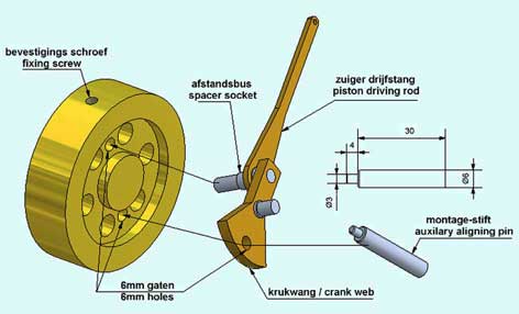
3. The crank shaft construction with the fly wheel (see picture 5)
The construction for the crank shaft with fly wheel is unusual and may be somewhat hazardous. The two eccentric axes on the crank webs with the driving rod big ends on it are recessed in the fly wheel and are fixed there with headless screws through the outer circumference of the fly wheel. So the fly wheel has no central bore nor an axis because the driving rods cannot pass such an axis of course. In fact the fly wheel is hanging in the outside ball bearings in what the short crank axes are turning around. You could say that the fly wheel at the same time is the third and central crank web that is normal for a crank shaft for two cylinder engines.
I could have chosen for a classic crankshaft for two piston rods and a fly wheels on the outside. But this solution is much more compact and is well possible for such a small engine as I did hope and experienced. And what's more, I like such little pranks.
To be able to mount the whole system wobble free I made some extra provisions: a 6mm hole in the broad part of the can web and an auxiliary aligning pin. The pitch between the long axis in the crank web and the 6mm hole is exactly equal to the pitch of two 6mm holes in the fly wheel; see drawing below.
To assemble the two cranks well aligned and wobble-free with the fly wheel follow the next procedure (see above figure):
1. Slide the piston driving rod and the spacer socket over the long axis of the crank web;
2. Insert this axis in one of the 6mm holes in the fly wheel;
3. Insert the auxiliary aligning pin through the 6mm hole in the crank web and in the other opposite 6mm hole in the fly wheel;
4. Fix the crank axis firmly with the locking screw in the fly wheel with a thin brass gland between the screw and the axis to avoid damaging the axis;
5. Remove the auxiliary aligning pin and repeat this procedure for the other crank; Here the short 3mm part of the aligning pin fits in a 3mm bore in the long axis of the other crank web.
In this way the short axes of the assembly are perfectly in line so the fly wheel will rotate wobble-free in the outer ball bearings in the crank supports.
4. The adjustment of the valve movements
The valves are pushed over the cylinder holes by the piston notches and pushed back again by the tumbler that is pushed by the opposite piston. The right adjustment of the valve strokes in relation to the cylinder holes is of utmost importance! It is a considerable critical and dynamic process with what the valve make a small floating stroke due to the 1mm clearance of the valve pins in the tumbler.
This adjustment can only be done with a not running engine as follows:
1. Turn the fly wheel slowly until the piston notch the valve has pushed away maximum. The valve must have opened the cylinder hole for 2/3 so it must be on 1mm distance from the hole rim.
2. Then turn the fly wheel until the piston is in its opposite position. With that the valve must be pushed back by the tumbler for only 1mm so the cylinder hole is still 1mm open. In that piston position push the tumbler to undo the 1mm clearance in the tumbler and then the valve must just close the cylinder hole. When the fly wheel is turned a little bit forwards and backwards (without touching the valve by the piston notch) one must see the valve sucked in the cylinder for 1mm due to the vacuum in the cylinder and be pushed back again in the other turn direction of the fly wheel.
If everything is made according to the drawing plan this automatically should be the adjusment. But it is well possible that it differs from that because of small dimension deviations like the distance from cylinder to crank shaft, a little too small or too big piston notch, etc.
In that case determine which dimension must be adapted to fulfil the adjustment requirements as described above.
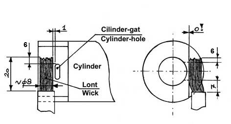
5. The spirits flame.
All flame-eaters can only run well when no false and cold air is sucked-in together with the hot flame gasses. That is the reason why the dimensions of the flame and its position in front of the hole in the cylinder is extremely important and sometimes very critical ! It determines the performance of the engine to a very high extent.
Because the flow pattern of the in streaming gasses depends on the geometries of the flame hole it it possible that the flame position must be another than exactly opposite to the hole. And that appeared to be the case here clearly! After a lot of experiments I could determine the optimal dimensions and the position of the wick in front of the flame hole. The construction of the burner itself is not important as long as the wick and its position satisfy the dimensions on the sketch below. I made this sketch for my 1-cylinder version but the situation for this 2-cylinder is the same.
Remarkable is the fact that the wick must be positioned clearly somewhat left from the flame hole. Most probably this is a result of the fact that the flame gasses are sucked-in under a certain angle. The 1mm dimension is an orientation value so it is possible that some small deviation must be made there. It is a matter of shifting the whole burner somewhat forth and back until you find its optimal place. Once found this position the engine will perform optimal and steady.
Denatured alcohol (96-98% ethanol) is preferable above spirits because the flame of it is hotter and it pollutes less. Spirits contains except ethanol also 2% methanol, 10% water and a some colouring agent. This denatured alcohol can be obtained in drug stores (at least in Holland)
!! Never use 100% methanol because it is very poisonous !!
6. Lubrication
This engine can run perfectly without any lubrication. What's more, it is my experience that piston lubrication with the common oil types (how thin they are) results in bad or not turning flame-eaters. Two reasons for that: viscous behaviour of the oil and deposits form burned oil residues on the cylinder and piston surfaces.
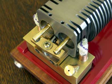
Lubrication with WD40 can have a positive effect but only when the engine is warm and when it tends to slow down for one reason or another. For that purpose I have made tiny lubrication holes in the upper side of the cylinder, see pictures 1 and 3. Providing a small dose of the thin and volatile WD40 there are no detrimental side effects as with common oil.
7.The surface cleaning of cylinder, pistons and valves
All flame-eaters suffer from internal pollution. Not amazing because the internal surfaces are constantly disposed to hot flame gasses of which residues and water vapour precipitate or react with the materials for cylinder and piston with increasing friction as a result. Especially for small engines this easily can lead to a poor performance or not running at all. The problem mostly occurs when the engine is cooled down after a run. If the engine refuses to restart after a good run one can take it for granted that a too high friction is the reason caused by deposits that must be removed. This cleaning with a cloth or paper impregnated with some solvent like WD40 is a rather easy if the cylinder/piston combination can be dismantled easily. For that reason I made a construction with what you can simply pull the cylinder vertically out of his supports on the mounting plate and pull out both pistons; see picture 6. The valves can be removed by unscrewing the tumbler support.
With graphite pistons and valves this maintenance is hardly or not necessary.
Starting-up the engine
Take care that the inside of the engine is clean and grease-free. If the engine is well made the whole system will turn smoothly around pushing the fly wheel by hand.
For your guidance:
- With removed valves the pistons must run in the cylinder for at least 8 to 10 seconds after you have pushed the fly wheel firmly;
- The complete system must make at least 10 strokes after you have pushed the fly wheel firmly.
Fill the tank of the burner with spirits or (preferably) with denatured alcohol and place the burner below the cylinder. Take care that the position and size of the wicks are as indicated on the sketch under point 5.
The engine must be started by pushing the fly wheel until the engine takes over. In general the engine will not start immediately because of water condense on and in the cylinder. This condense will disappear after 1 minute or less and the engine will start running after that. If this is not the case play a little with the position of the wicks by sliding the burner a little back and forwards and/or bending the wicks with a tweezers.
The engine will keep running until the burner is empty which will be the case after some 15 minutes.
As said, it may be good to put some WD40 droplets in the greasing holes when the engine is hot and if the engine tends to slow down. As long as the engine runs perfectly this greasing can better be ommited to avoid internal pollution as much as possible. Remarkable is the fact that the engine seems to have no problem with this kind of pollution as long as it is running. It looks as if the flame gasses don't have the time to deposit their residues and/or that the polluting gasses are pushed out continuously.
Stop the engine before the tank is completely empty because the wick cotton will burn to carbon immediately when it is drying-up. The flame will grow smaller very fast and the engine stops. A burned wick will produce a poor flame and the engine will not run well on that. If the wick is burned with visible carbon on it you have to replace it by a new one. Another indication for the crucial role the flame plays for a good performance of a flame-eater.
The performance of the engine
About the performance of this engine in fact not much more can be said than that its maximum speed is about 800 to 900 rpm and that its power is too low to drive something more significant than its own mechanism. But it is fascinating to see spinning it around with a lot of noise caused by the pistons while pushing the valves and the tapping noise of the tumbler. It is a matter of taste of course but I like the tough commotion that this little thing is making.
The advantages of this internal head valve design
This design has several advantages compared to the classic construction with external head valve:
1. The rather precarious mechanism with a driving rod on a cam disk and external valve with springs is eliminated completely and with that the critical adjustments for the cam discs, the spring pressures on cams and head valves and the timing of these mechanisms are eliminated.
2. The airtight sealing of the internal head valves is simply a matter of making a good fitting in the cylinder just as for the working pistons;
3. A restraining overpressure in the cylinder cannot occur because the valve opens the cylinder hole automatically at the moment the pressure equals the open air pressure. The occurrence of a temporary over pressure is one of the important reasons of poor performance for flame-eaters with external valve.
4. The friction of the internal head valve in the cylinder is considerable lower than that of the complete mechanism for the external valve and no spring pressures must be gained;
5. The temperature of the internal valve is lower than that of the external one. The last is radiated directly by the burner, as well as the spring that must keep this external valve tight to the surface of the cylinder.
6. The adjustment of the parameters for the best engine performance is implicit anchored in the dimensions of the design. In other words, there is nothing left at all to adjust so nothing can drift away.
7. Because of symmetry this engine runs in both directions. May be not an explicit advantage, but it is remarkable anyway;
8. This design is extremely simple and robust with a minimum of parts which all are easy to make. It is a suitable model for not very experienced model builders I think.
The drawing plan
I made a CAD drawing plan for this flame-eater, available for every one interested; click here for a request.
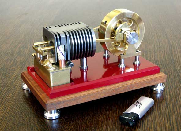
Picture 1
Picture
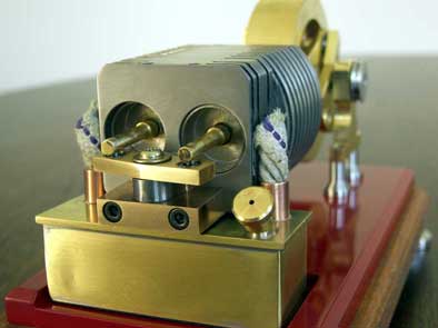
2
Picture 3
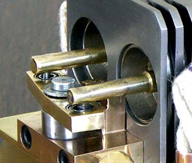
Picture 4
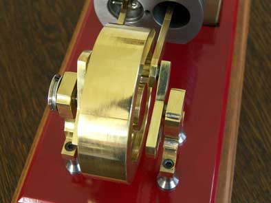
Picture 5
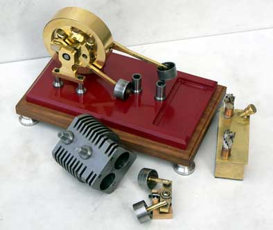
Picture 6
Nice replica by Gerard Versluys:
Nice replica masde by
Arnaud Sully:
Nice replica made by
Hans Vingerhoets: