Introduction
In principle the cold compression in an IC (model) engine can be calculated from the total cylinder volume and the stroke of the piston in the cylinder. But in practice this pressure can be lower because of leakages along the piston and/or leakages at any other place in the system such as the valves, cylinder head gasket, spark plug, etc. It also can happen that the compression is made too high and mainly small engines can suffer from that. It is my experience that for this kind of small model engines the best compression is anywhere between 3 to 5 ato.
Mainly in case of troubles that might be related to the compression it is important to measure the real compression pressure in the cylinder. This pressure in the cylinder of an IC engine very dynamic, but in fact it is only important to know the maximum pressure when the piston is at its TDP when the ignition occurs. Of course air-pressure gauges exists but most model builders don't have them or they are not suitable for this purpose. Furthermore these kind of gauges mostly are mechanical dial instruments from what the needle pointer will swing violently back and forth due to the strongly alternating pressures in the cylinder when the engine is turning around, for instance with a hand drilling machine. So with this kind of instruments it is hardly or not possible to measure the exact maximum compression.
So I made an extreme simple but well working little device with what the maximum occurring compression in the cylinder can be measured in a very easy but fairly accurate way. It is so simple that it will not be any problem for every model builder to make this little device themselves.
The working principle
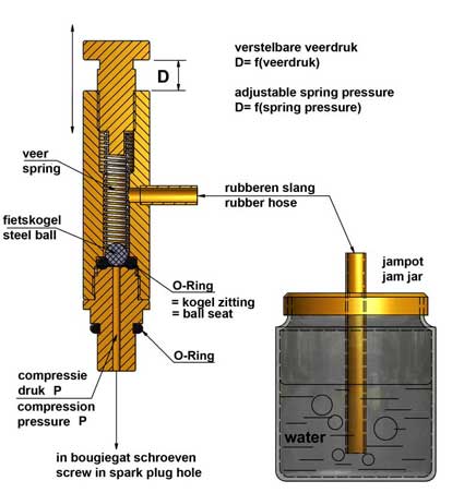
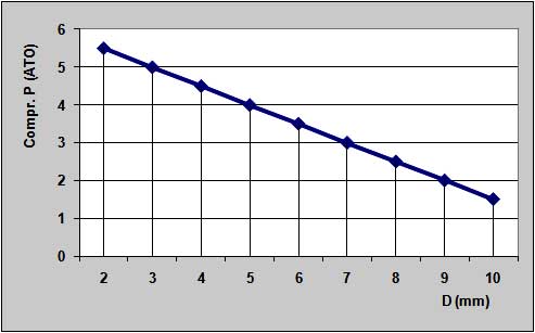
Fig.1As shown in figure 1 the system consists of a little ball valve that must be screwed in the cylinder head instead of the spark plug and from what the exit is connected with a rubber hose to a jam jar with some water in it. The spring pressure on the steel ball can be varied with a screw able pivot on top of the ball valve. At the moment the compression pressure (P) below the ball is equal or a fraction higher than the spring pressure the ball will be lifted from its seat, causing sudden air-bubbles in the jam jar. The compression pressure that causes this effect can be derived from the measure "D" if the relation between "D" and the pressure that lifts the ball is determined before. This linear relation can be determined once and simple by connecting the ball valve to a compressor with adjustable and readable static air pressures. Measuring the distance "D" with a caliper at different adjusted air pressures when the ball is just lifted one can make a table or graph from what the gas pressure can be read at a certain values of "D". Figure 2 shows such a relation, valid for my ball valve.
Fig. 2The slope of the line will be dependent on the stiffness of the used spring; the more rigid the spring, the more upright the line will be.
The work-out
Because the ball valve must be screwed in the cylinder head the tread must be the same as that from the used spark plug. It is of course also possible to make a reducing piece in case one has to do with different thread types. In all cases one must take care for good sealing with rubber O-rings.
The global dimensions of the ball valve will be about the same as the spark plug; the lenghts will be somewhat bigger. With that the dimensions of the ball and the spring are more or less determined because they must fit in the ball valve housing. I used the standard steel (bicycle) ball with diameter 3/16 inch. The spring has a 4mm inner diameter and with the wire diameter of 0.6mm the outer diameter is about 5.2mm. The stretched lenghts of the spring is about 35mm. The maximum pressure of this spring is about 1 kgf when it is totally depressed. One can use a somewhat deviating spring as long as the spring pressure is in the same order of magnitude.
The force below the ball equals PxO, where P is the compression pressure and O is the cross section of the ball seat. I wanted a measuring range of about 2 to 6 ato and a simple calculation learned me that the seat diameter then must be 3.5mm, using my available spring. Originally I only made a bore in the brass housing on what the ball rested. But especially with low spring pressures this didn't seal for 100% causing little and inconvenient bubbles in the jam jar while the ball wan not lifted by the gas pressure below the ball. Therefore I changed this by using a rubber O-ring for the ball seat. This O-ring has a 9mm outer diameter and a hole diameter of 3mm. On that the ball rests on the right circle of about 3.5mm. The graph of figure 2 as a result of the calibration proves that this theory was according to the practice. For this calibration I used my refrigerator compressor that can make a maximum static pressure of 6 ato and on what I connected a manometer from a bicycle pump.I made the bore below the ball very small (1.5mm) to add a neglectable small volume to the cylinder content.
One could fit a kind of pointer on the pivot to indicate the stroke of the pivot with some scale division on the ball valve housing, but making such a scale is not that easy and measuring the dimension "D" with a caliper is more easy and more accurate in my opinion.
The half filled jam jar with water with the central tube and a vent hole in the lid is not only extremely simple but also a perfect means to indicate the moment the ball is lifted from its seat. Of course the dimensions of this jam jar are not important at all.The measuring procedure
Remove the spark plug and screw in the ball valve instead. Connect the ball valve to the jam jar with a rubber hose. Turn the engine with a hand drilling machine and screw in the pivot on top of the ball valve until no bubbles occur in the jam jar; then the compression pressure is lower than the spring pressure on the ball. Gradually screw out the pivot (with turning engine) until suddenly bubbles occur in the jam jar. That is the situation where the compression pressure just is lifting the ball. Measure the dimension "D" and read the corresponding pressure on the calibration graph. This is the maximum compression pressure in the cylinder you wanted to know.
See also the video below:
Some results
With this little device I measured the compression of all my IC engines. They vary between 2 and 4 ato which was according to my expectations. But the compression of one engine was even more than 6 ato. It is the 4-stroke engine with rotary valves with what I have some troubles from time to time: the valve discs are pushed somewhat from each other making the engine unreliable. One has to realize that the combustion pressure is about 4.5 times higher than the cold compression, so then we are speaking about peak pressures of 20 to 30 ato! In fact this problem was the reason why I developed this pressure measuring device. Maybe I now can make this engine reliable by reducing the cold compression to a more acceptable level; we'll see.
Drawing plan
For this ball valve measuring gauge I made a 2-sheet drawing plan available for everyone interested.