1. The Atkinson principle.
Typical for the Atkinson is that the four piston strokes (intake, compression, power and exhaust) are made with only one revolution of the flywheel, other than the 2 revolutions turns with the normal (Otto) 4-stroke. The distribution between the crankshaft and the valve system is therefore 1 to 1 instead of 2 to 1. An important feature is also that the exhaust stroke is greater than the other three strokes. This makes it possible to drive the piston at the end of the exhaust stroke by a hair thickness against the cylinder head so virtually all the burnt gases are driven out of the cylinder. In the normal 4-stroke the distance of the piston to the cylinder head is, by definition, equal to the distance at the moment of maximum compression. Since I prefer to work with fairly low compression for easy starting and a quiet running behaviour this volume of the combustion chamber at a normal 4-stroke is still about 20% of the cylinder volume so with a normal 4-stroke this percentage of the burned gasses remains in behind the cylinder at the moment the fresh gas mixture from the carburettor is sucked-in again. With industrial 4-stroke engines, there are various techniques for reducing the impact of this dead space, but this is difficult to achieve for simple IC models .
As a result the cylinder charge in the Atkinson cylinder is much more pure, which will result in a more efficient combustion. In fact the efficiency is not that important for small model engines, but a better combustion of the purer gas mixture will contribute to a more reliable running behavor for sure.
An important disadvantage of the Atkinson is the rather complex driving system with quite abrupt reverse movements, causing a more violent running behaviour. Apart from the fact that it is hard to make this system compact the balancing of it is extremely difficult. As far as I know, this is the most important reason why the Atkinson principle in the industrial practice has lost it from Otto principle, while both systems are almost simultaneously designed in the second half of the 19th century. However, for a model engine this disadvantage is no real objection; it is exciting to see how this Atkinson driving system makes these typical piston movements.2. De Atkinson MK1 version
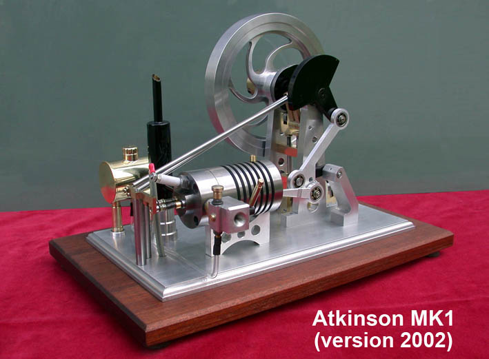
Already in 2002 I made my first MK1 version of an Atkinson engine according to the plans of a colleague model builder. I made some changes, mainly to improve the rather violent behaviour of this engine; see the picture below.
In 2006 I implemented some further improvements and in 2016 I made the CAD plans for this MK1 version again with some minoe improvements; see the concerning page for this MK1 / 2016 version.
3. The MK2 version of this Atkinson
In 2010 I made a complete changed MK2 redesign for two reasons:
1. This MK1 version runs rather well and reliable but the behavior is nevertheless still too impetuous in my opinion. This is partly due to the abrupt reversal movements of the typical Atkinson connecting rod system but also to the system with the two rocker arms with the very long pushing rods. With this MK2 design I eliminated the rocker arms and the two long pushing rods by making a overhead cam shaft directly against the two poppet valves as I earlier did with my Otto 4-stroke engine. This overhead cams are driven by a geared belt connecting the flywheel axle and this cam shaft with two gear wheels with the same number of teeth.
2. I have replaced the difficult to adjust classic carburettor by my "Petrol Vapour Carburettor" which I use with success in all my engines.
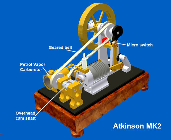
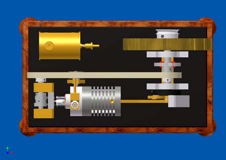
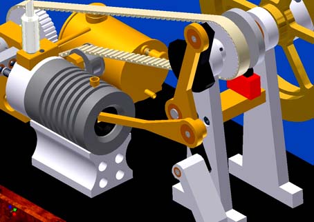
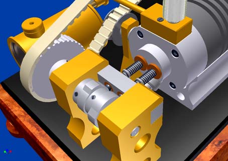
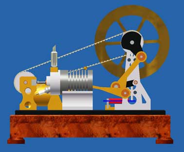
The figure below illustrates this MK2 design:
There are also some minor changes such as an integrated piece on the cylinder head for the intake and exhaust, a simplyfied (cosmetic) muffler and higer wooden base in what a high tension coil for the spark ignition can be build.
I have made a CAD drawing package for this MK2 version and updated that recently June 2016. This plans are available for every-one interested; click here for a requestStrangely enough I only designed this MK2 version but I did not (yet) made the engine myself. The reason is that shortly after the the MK2 version I made a third (MK3) version with a rotary valve in the cylinder head and this MK3 version I did make; click here for the concerning page. That's why I can not show you here my own life video of this MK2 version but I can do this for the videos from various modelling colleagues such as Lorenzo Porro, TJ Willis, Anton and Gerard Grieder Versluys; see the right-hand frame of the page.
See also the detailed report of Petr, making his MK2 replica:
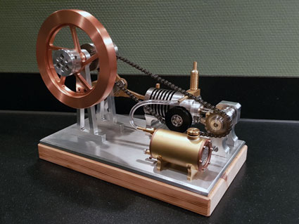
http://s191.photobucket.com/albums/z173/RaceSoft/Atkinson%20engine/Below a picture of the very nice replica made by Lorenzo Porro:
General remarks
1. For the cylinder as well as for the piston I used cast iron. In this case this material is at least highly preferable, may be even conditional. The expansion of cast iron is very low and in any case equal for cylinder and piston. Together with the fact that it is more or less self-greasing due to the relative high carbon grade, it prevents jamming of the piston, even whithout oil greasing!
Furthermore cast iron is highly temperature resistant and working up is rather easy. The engine will run even without a piston ring if the surfaces of the piston and the drilling in the cylinder are made accurate and smooth.
2. The cylinder temperature don't exceed 110ºC after 15 minutes runtime and at speed below 800 rpm. Since I never be in the need for longer run times and higher speed there is no reason to add a complex watercooling system under this conditions. Generally 10 minutes runtime is more than enough for a successful demonstration.
3. At some 10mm from the bottom of the cylinder I made a small and transverse bore-hole of about 2mm. From time to time I put one drop of oil in it, not necessary to avoid jamming but for my feeling that it will keep the piston and cylinder surfaces in a "good condition".
Some technical specifications
Global dimensions: lxbxh= 350x200x250mm;
Cylinder: bore 24mm, length 61mm, perlytisch cast iron;
Zuiger: diameter 24mm, length 28mm, perlytisch cast iron;
Piston strokes: intake ca 26mm, compression ca 21mm, power ca 29mm, exhaust ca 34mm.
Flywheel: diameter 155m, width 20mm, aluminium or (preferably) steel;
Revolution speed: adjustable between ca 300 and 800 rpm;
Fuel: normal petrol for auto cars without oil addition or preferably Coleman Fuel.
Video with beautiful replica made by
Lorenzo Porro
Nice replica made by TJ Willis
Replica made by Anton Grieder:
Replica made by Gerhard Versluys: