Introduction
In 2002 I made my first Atkinson 4-stroke engine MK1; see the concerning page. In 2010 I designed a second (MK2) version; see the concerning page.
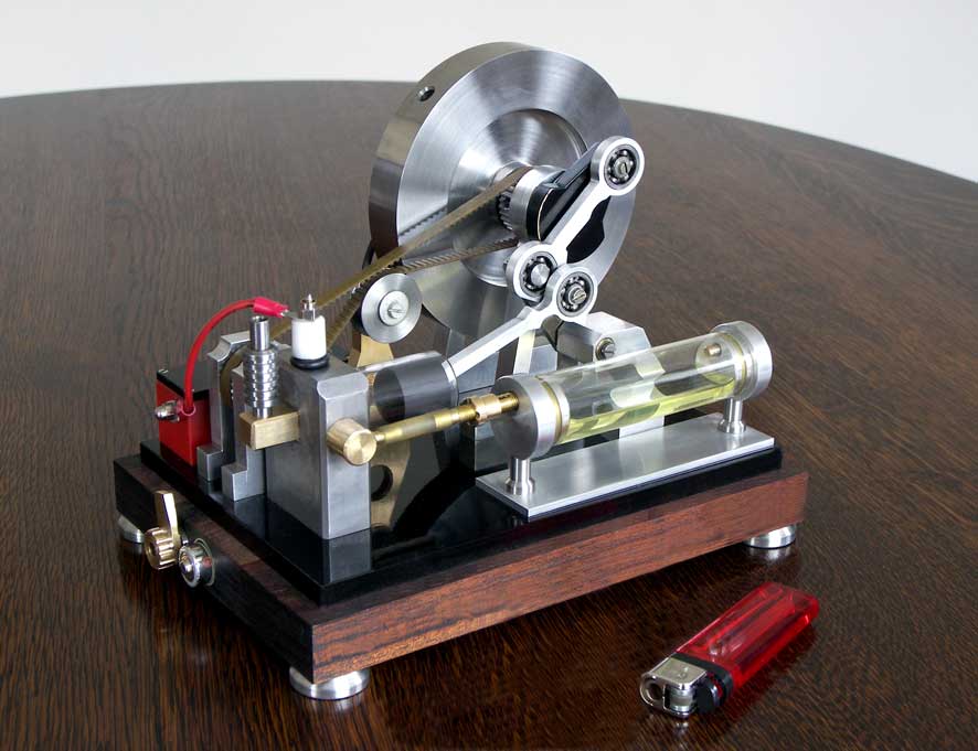
Encouraged by my successful experiences with a rotary intake & exhaust valve and a glass cylinder with graphite piston with some of my other IC engines I made a design for a third MK3 version:
This MK3 version is 40% smaller than its predecessors. Further main differences are:
- A very simple rotary valve in the cylinder head instead of two reciprocating valves with cam drive system;
- A glass cylinder containing a graphite piston;
- A self made miniature electronic ignition circuit.
This more compact Atkinson is running a lot less boisterous than its predecessors, mainly because this continuously rotating valve will not cause any shock loads as conventional poppet valve systems with cam discs, pushers and rockers do. The very low friction of the graphite piston in the glass cylinder (without any lubrication!) also contributes to a smoother running behaviour. Another advantage is the much simpler overall construction.
The visible combustion fires through the glass cylinder also adds something special to this MK3 version.The design
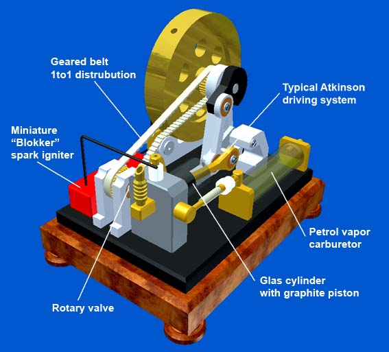
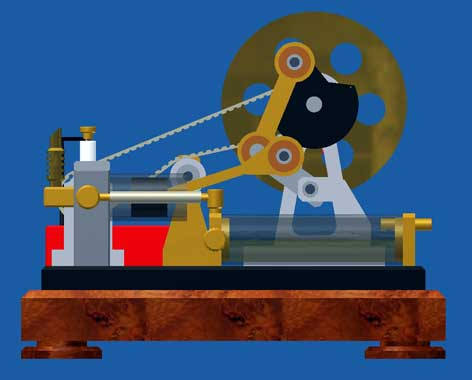
1. The Atkinson principle.
Typical for the Atkinson is that the four piston strokes (intake, compression, power and exhaust) are made with only one revolution of the flywheel, other than the 2 revolutions turns with the normal (Otto) 4-stroke. The distribution between the crankshaft and the valve system is therefore 1 to 1 instead of 2 to 1. An important feature is also that the exhaust stroke is greater than the other three strokes. This makes it possible to drive the piston at the end of the exhaust stroke by a hair thickness against the cylinder head so virtually all the burnt gases are driven out of the cylinder. In the normal 4-stroke the distance of the piston to the cylinder head is, by definition, equal to the distance at the moment of maximum compression. Since I prefer to work with fairly low compression for easy starting and a quiet running behaviour this volume of the combustion chamber at a normal 4-stroke is still about 20% of the cylinder volume so with a normal 4-stroke this percentage of the burned gasses remains in behind the cylinder at the moment the fresh gas mixture from the carburettor is sucked-in again. With industrial 4-stroke engines, there are various techniques for reducing the impact of this dead space, but this is difficult to achieve for simple IC models .
As a result the cylinder charge in the Atkinson cylinder is much more pure, which will result in a more efficient combustion. In fact the efficiency is not that important for small model engines, but a better combustion of the purer gas mixture will contribute to a more reliable running behavor for sure.
An important disadvantage of the Atkinson is the rather complex driving system with quite abrupt reverse movements, causing a more violent running behaviour. Apart from the fact that it is hard to make this system compact the balancing of it is extremely difficult. As far as I know, this is the most important reason why the Atkinson principle in the industrial practice has lost it from Otto principle, while both systems are almost simultaneously designed in the second half of the 19th century. However, for a model engine this disadvantage is no real objection; it is exciting to see how this Atkinson driving system makes these typical piston movements.2. The rotary valve.
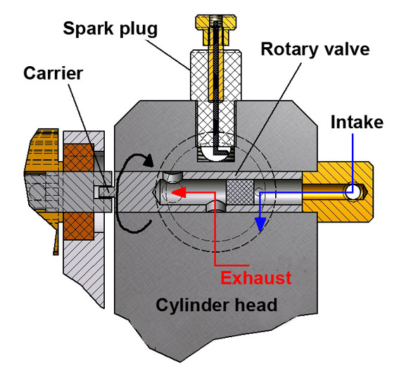
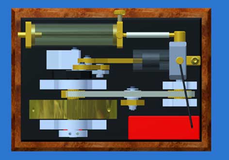
In fact the rotating intake and exhaust valve is a simple standard 8mm axle having a central bore and three radial bores. Between the bore for the inlet and two bores for the exhaust a steel prop is pressed to separate the inlet and the exhaust from each other. This valve mandrel fits with H6 fit into an 8mm hole through the cylinder head and is driven by the shaft on what the lower timing belt wheel is fixed. I have chosen for this carrier system between the two axles instead of one continuous shaft to avoid side way loading of the mandrel that would cause wearing between the mandrel and the bore in the cylinder head. I have applied this principle successfully with some other of my previous 4-stroke engines.
The angular shift between the bores for the inlet and for the exhaust must be be such that the inlet and the exhaust occur at the appropriate moments in the four-stroke process. That was a nice puzzle because with the Atkinson the angular rotation of the crankshaft relative to the piston movements are not symmetrical. But while using the CAD assembly in the various relevant piston positions I could determine the correct angle shifts between the inlet and exhaust bores in the valve mandrel. They are a little bit different from the what the above cross section suggests, this to keep this picture more readable.
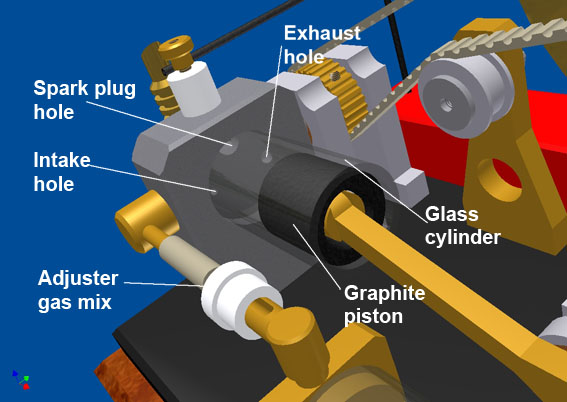
3. The glass cylinder and graphite piston.
Recently I have made five engines with a glass cylinder containing a graphite piston and that with perfect results so I applied that here again.
I cut the cylinder out of a glass 20ml "Fortuna Optima" syringe with wall thickness 2mm and with an exceptional high accurate inner diameter tolerance: + / - 0.01 mm or better. I simply glued the cylinder head in a 5mm deep chamber with Loctite 603 and after curing during some half an hour at about 50 degrees Celsius it results in an absolutely unshakable and air-tight connection.
I turned the graphite piston on a metal mandrel in the three claw clutch of my lathe in such a way that the piston fits in the cylinder with a clearance of about 0.01 (0.02mm maximum). The piston then runs with neglect able friction in the glass cylinder and is doing that continuously without any lubrication!
This glass and also the graphite are not really everyday materials, although with some searching you can certainly will find suppliers for that on internet.
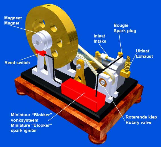
4. The spark ignition.
For the spark ignition I again used the customized miniature circuit from the "Blokker" gas lighter, see the concerning page. A neodymium magnet in the aluminium start-up pulley runs along a reed switch that controls the sparks at the right moments in the process.
5 The carburettor.
The carburettor is a somewhat special version of the "Petrol Vapor Carburettor" as I have previously applied a few times for other IC models; actually nothing new and therefore no problem.
I later have modified the air regulator as you still see on the pictures and the video on this page because it appeared to be rather critical. The new regulator now is in the line between the carburettor and the cylinder head and I changed the drawing package accordingly.
Starting-up the engine and its behaviour
The engine starts easily with a few manual turns on the flywheel if the carburettor once is properly adjusted. Especially with fresh auto car gasoline a too rich gas mixture easily occurs, caused by a volatile component in gasoline in which case a yellow combustion fire can be seen through the glass cylinder. With that carburettor adjustment the engine runs poorly or not at all. One should therefore open the controller for the extra air first completely during the start-up with a hand drill and then very gradually decreasing the extra air until the engine takes over with a blue combustion colour. If one screws-in the controller more one will see a yellow colour arising, indicating that the mixture has become too rich so one has to withdrawn the controller somewhat again until the yellow colour disappears. Around this setting point of the carburettor (with the light blue colour) the engine will run best.
The speed of about 450 revolutions per minute is relatively low and it strikes me that this can be hardly influenced by carburettor settings. My explanation for this is that the engine speed is mainly determined by the "half-moon" effect of the bores in the rotary valve of which the diameters are quite small, in particular those for the inlets bores. At high speeds, the filling of the cylinder will decrease thereby, making the engine to start running slower automatically. Accordingly, a certain naturally balance will occur with this stable and relatively low speed. I think that's fine because I do like low speeds for these small models and especially for the Atkinson with the complex driving system. This in contrary to my first Atkinson that I must cling on the table not to shake off. This MK3 version does not come a millimetre of its place and is extremely quit, making its turns like a slow diesel engine.
So I am very pleased with the outcome and here also the combustion process is again nicely visible through the glass cylinder when the ambient light is somewhat tempered; see the video below.
The drawing plans are available for everyone interested; click here for a request.
Alternative for the glass cylinder
If one cannot obtain this very special glass (not unlikely) and/or graphite one can make the cylinder for instance from bronze and the piston from cast iron. Well made (fairly leak free and with low friction) the engine will run also well. The only difference will be that the combustion fires will not be visible; pity of course, but the rest of the engine is the same.
Nice replica's by Jaap van Wijk:
Beautiful replica made by
Bart van Duin: