1. The Atkinson principle.
Typical for the Atkinson process is that the four piston strokes (intake, compression, power and exhaust) are made with only one revolution of the flywheel, other than the 2 revolutions turns with the normal (Otto) 4-stroke. The distribution between the crankshaft and the valve system is therefore 1 to 1 instead of 2 to 1. An important feature is also that the exhaust stroke is greater than the other three strokes. This makes it possible to drive the piston at the end of the exhaust stroke by a hair thickness against the cylinder head so virtually all the burnt gases are driven out of the cylinder. In the normal (Otto) 4-stroke the distance of the piston to the cylinder head is, by definition, equal to the distance at the moment of maximum compression. Since I prefer to work with fairly low compression for easy starting and a quiet running behavior this volume of the combustion chamber at a normal Otto 4-stroke is still about 20% of the cylinder volume so with a normal 4-stroke this percentage of the burned gasses remains in behind the cylinder at the moment the fresh gas mixture from the carburetor is sucked-in again. With industrial 4-stroke engines, there are various techniques for reducing the impact of this dead space, but this is difficult to achieve this for simple IC models .
As a result the cylinder load in the Atkinson cylinder is much more pure, which will result in a more efficient combustion. In fact the efficiency is not that important for small model engines, but a better combustion of the purer gas mixture will contribute to a more reliable running behavor for sure.
An important disadvantage of the Atkinson is the rather complex driving system with quite abrupt reverse movements, causing a more violent running behavior. Apart from the fact that it is hard to make this system compact the balancing of it is extremely difficult. As far as I know, this is the most important reason why the Atkinson principle in the industrial practice has lost it from Otto principle, while both systems are almost simultaneously designed in the second half of the 19th century. However, for a model engine this disadvantage is no real objection; it is exciting to see how this Atkinson driving system makes these typical piston movements.2. De Atkinson MK1; old version 2002
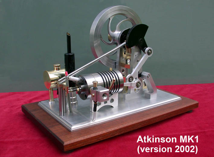
Already in 2002 I made my first MK1 version of an Atkinson engine, see the picture below:
I had to make this first version MK1 in accordance to drawings and descriptions of a colleague model builder Kees Goverde and because of "copyright" I did not make a CAD drawing package thereof at that time.
Building this engine was relatively simple because there are no really difficult parts and one can make it by only lathing and milling standard materials; it took me about 80 net man-hours.
After a lot of attempts and experiments I succeed in to let running the engine. But it ran only with very high speed (2000 to 3000 rpm) with the result that the machine-behavior was very violent due to the abrupt and multiple reverse movements of this special driving system. I had to fix the engine on my working table to keep it on place. A more serious problem was that the enormous forces damaged several parts of the whole driving system.
Changes I made to improve the engine behavior
Strengthening the driving system.
To avoid the mentioned damaging I first introduced some strengthening in the mechanical system, as hard soldering the crank on the (thicker) 12mm flywheel axis and making the main part of the driving rod system out of one piece of 6mm thick aluminum. Finally everything stays alive, but the very wild behavior remained of course."Taming" the engine
I was convinced that I only could "tame" this wild guy by reducing the revolution speed significantly. It turned out that this was not only possible through any adjustment of the classic carburetor, because the engine always stopped running at speeds below 2000 rpm. There were no other adjustments possible such as changing the timing for the intake valve versus the exhaust valve, because the original design is based on a self-sucking intake system. That means that the intake-valve is not driven by a push rod against a camshaft but that it has only a weak spring that closes this intake valve as long as the pressure in the cylinder is equal or higher than the atmospheric pressure outside. The determination of the correct spring strength is therefore rather critical: too low means leakage, too high means no intake of the fuel mix from the carburetor.
So I decided to add a second pushing system for the intake valve, similar to that of the pushing system for the exhaust valve. There was just enough space for adding a second cam on the cam shaft. Except for the possibility to adjust any different timing, the spring on the intake valve can be chosen now a lot stronger to be sure of a 100% closing. The camshaft can easily perform the needed force to open this intake valve.
Experiments provides me the best cycle timing at which the engine runs at much lower speed of about 500 rpm. I did this measurements with a protractor on the fly wheel:
0º Upper position of the piston; intake valve starts to open;
75º Inlet valve is completely closed. The gas mix in the cylinder is compressed after 135º;
140º Spark, 5º after the upper position of the piston. An earlier spark can cause backstroke with the relative low speed of this engine;
220º Exhaust valve starts opening; also about 10º before the lowest position of the piston;
355º Exhaust valve completely closed, also at the same moment at which the inlet valve opens.
With this change the engine behavior is well acceptable. It stays on place on the table with revolution speeds between 300 and 800 rpm. But it stays more or less tempestuous, but it is exiting to see this guy running!
2. Improved version of the MK1 Atkinson (2016)
For 8 years long I kept this Atkinson MK1 as it was and as described above. During that time I designed and made several other models of IC engines. But it was all along a little nibble to me that this Atkinson was an engine with a pretty violent running behavior, especially compared to the other little IC combustion engines I made in those 8 years.
In 2010 I realized that an Atkinson with a geared belt drive (instead of the very long pushing rods) and with an over head cam close to the cylinder head most probably might run much more quiet. With that in mind I designed the MK2 version; see the concerning page for this MK2 version. Since I also build experience with rotary valves with other 4-stroke models, I shortly after that designed and made a third (MK3) version with geared belt and rotary valve in the cylinder head; see the concerning page for that MK3 version. This MK2 and especially the MK3 version have a significantly better dynamic behavior because of the smooth running geared belt and especially the rotary valve that don't cause any impact loads on the system.
However, I still regularly got requests for plans for the MK1 version, mainly because many modelers apparently have problems obtaining suitable geared belts and making the geared cog wheels for that. Shortly (June 2016) I decided to make a complete new CAD drawing package for this MK1 version. I implemented thereby also a number of improvements, using all experiences that I have built over the years with all my other combustion engines; it was implementing "progressive views" so to speak.
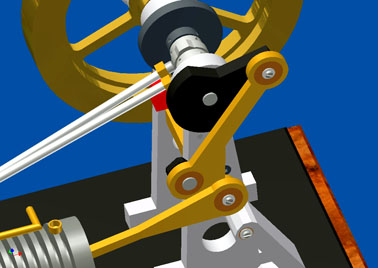
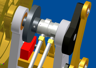
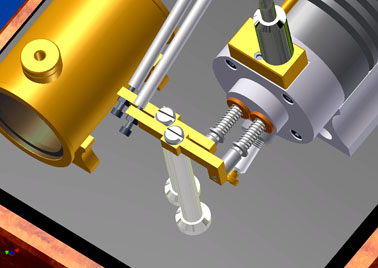
The CAD figure below shows the result for this revised MK1 version:
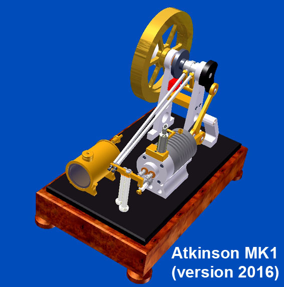
General remarks
1. For the cylinder as well as for the piston I used gray cast iron (type GG25). In this case this material is at least highly preferable, maybe even conditional. The thermal expansion of this cast iron is very low and in any case equal for cylinder and piston. Together with the fact that it is almost wear-free and more or less self-greasing due to the relative high carbon grade it prevents jamming of the piston, even whithout oil greasing!
Furthermore cast iron is highly temperature resistant and working up is rather easy. The engine will run even without a piston ring if the surfaces of the piston and the the cylinder hole are made accurate and with small clearance and smooth surfaces.
2. The cylinder temperature don't exceed 110ºC after a run time of 15 minutes. Since I never be in the need for longer run times there is no reason to add a complex water cooling system under this conditions. Generally 10 minutes run time is more than enough for a successful demonstration in my opinion.
3. At some 10mm from the bottom of the cylinder I made a small and transverse bore-hole of about 1mm with a little oil pot in it. From time to time I put one drop of oil or WD40 in it, not necessary to avoid jamming but to keep the piston and cylinder surfaces in a "good condition", especially preferable when the engine is stored for a long time.The most important characteristics, resp. improvements:
1. Applying the "Petrol Vapor Carburetor" instead of the conventional venturi carburetor; see the benefits of this carburetor on the concerning page.
2. A flywheel made of steel or brass instead of aluminum with a considerately smaller diameter.
3. A terminal connection block on the cylinder head for both the intake of the gas mixture from the carburetor and for the exhaust of the burnt gases. The much smaller (cosmetic) muffler could therefore be screwed directly to this terminal block.
4. A higher wood base in what a not too large bobbin (high tension coil) of a (classic) car or motorcycle can be mounted. This is of course also possible with a smaller spark system like the electronic "Blokker" circuit; see the concerning page.Some technical specifications
Global dimensions: lxbxh= 320x190x230mm;
Cylinder: bore 24mm, length 65mm, pearlytic grey cast iron;
Piston: diameter 24mm, length 28mm, pearlytic grey cast iron;
Piston strokes: intake ca 26mm, compression ca 21mm, power ca 29mm, exhaust ca 34mm.
Flywheel: diameter 150m, width 20mm, steel or brass;
Revolution speed: adjustable between ca 300 and 800 rpm;
Fuel: standard unleaded gasoline for auto cars without oil addition or (prefeably) Coleman Fuel.
CAD plans
For this strongly revised MK1 2016 version I made a complete CAD drawing package that is available for everyone interested; click here for a request.
Although I did make the CAD plans for this MK1 2016 version I did not make the engine myself for the moment so I cannot show a video of it. I hesitate a bit to do that because I then have a little feeling of making the same engine twice, although this 2016 version will be substantially better than the one I made 14 years ago.
Nice replica made by
Immo Drust: