The reason for this project.
With a 3D printer, a plastic filament (wire) is led to a heated nozzle where this plastic melts on the spot. The liquid material is extruded layer by layer to form the object to be printed. Printing is done in layers, per layer the head is controlled in two directions according to a drawing pattern that has been inserted into a processor. Thus the intended 3-dimensional object is created.
The filament is on a spool and is gradually unwound from it to the nozzle during the spraying process. It is actually always the case that eventually a situation arises in which a remnant of the filament on the spool is too little for a new object to be made, so that it is in fact lost, which goes against the feeling of useful use of materials.
My son-in-law Maarten has such a 3D printer and was looking for a method in which such a remnant of a filament can be melted onto the beginning of a new filament in such a way that the resulting weld can pass through the nozzle without any problem. Because he couldn't find anything like that anywhere on the internet, he asked me (as a model builder) if I had an idea how this could be done.
In the past I have made drive belts where I melted the ends of a straight piece of plastic wire together by pressing it against a thin and heated metal plate and then pressing the melted ends together. Based on this principle I have now made a setup for the "cup-butt" melting together of 3D printer filaments.The design of this filament fuser.
In this case, the challenge was to fuse the relatively thin filaments with a diameter of 1.75mm in such a way that their center lines would lie nicely on top of each other to allow the weld to run smoothly through the nozzle of the 3D printer. Manually, as I did with the less critical drive belts, this would almost certainly not produce the desired result here.The rider unit.
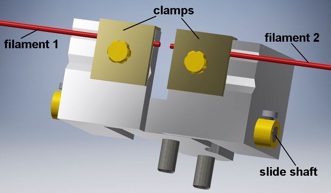
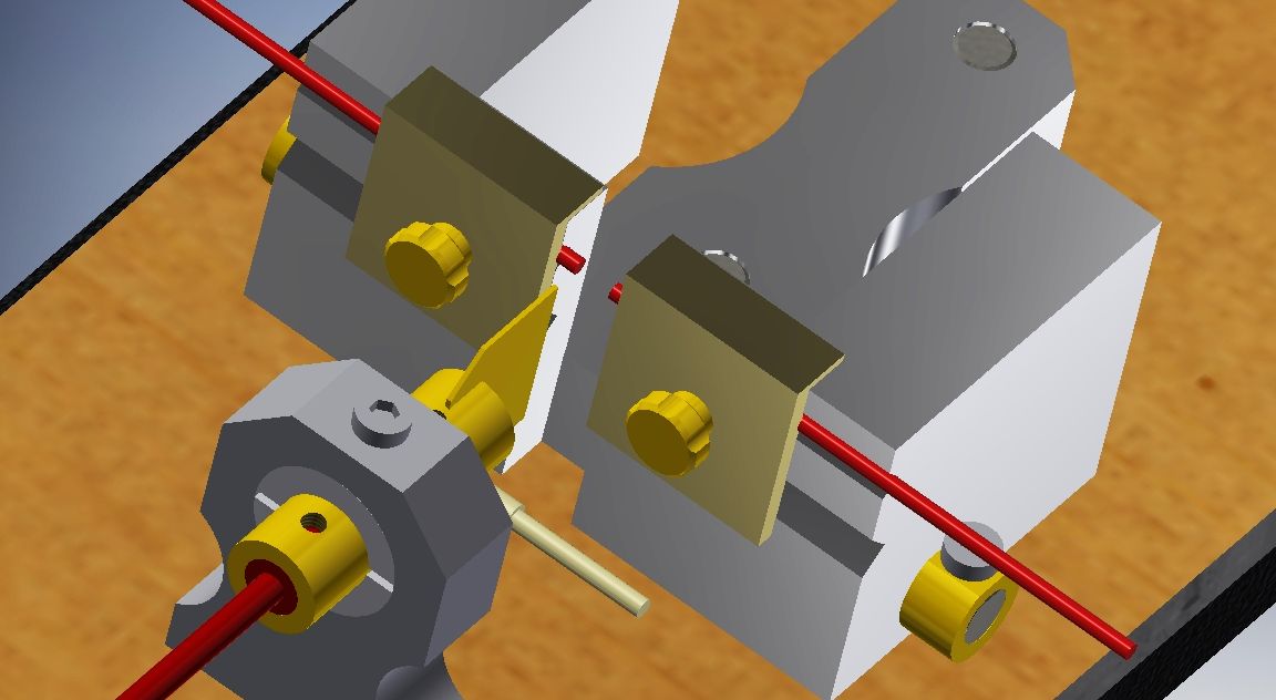
I therefore decided to make a unit with two aluminum blocks (hereinafter referred to as "riders") in which there are two V-shaped slots at exactly the same heights in which the two filaments to be welded together can be clamped with pressure plates. For the also common thicker filaments with a diameter of 2.85mm, I also made a second set of slots with a proportionally greater depth. Those filaments can be clamped by the same pressure plates.
These two riders both sit on the same slide shaft on which they can be moved apart or towards each other in a horizontal direction. The filaments protrude only about 2mm beyond the clamping plates, so that it is almost impossible for the center lines of the filaments not to lie exactly on top of each other. The filaments as they come off the spool are somewhat curved and it is therefore advisable to first straighten the parts that are clamped onto the riders as best as possible, otherwise the 2mm ends could still make an undesirably small angle with each other.
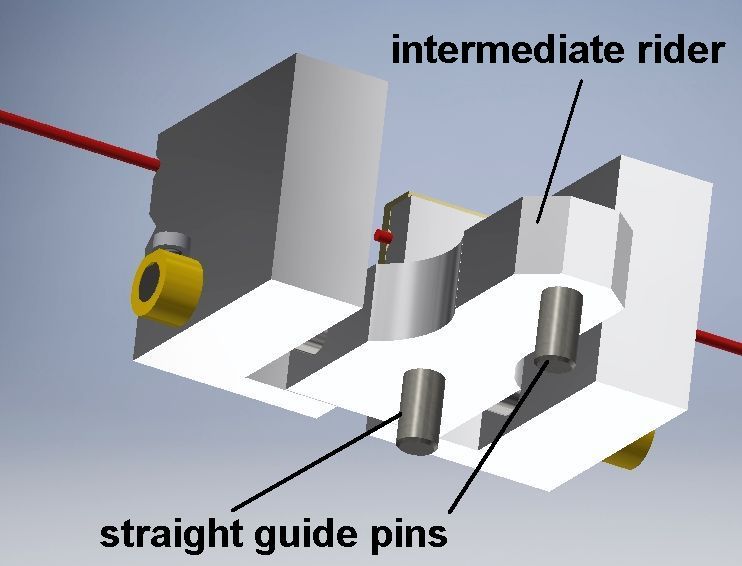
Between the two riders for the filaments there is a third intermediate rider that is screwed onto the same slide shaft.
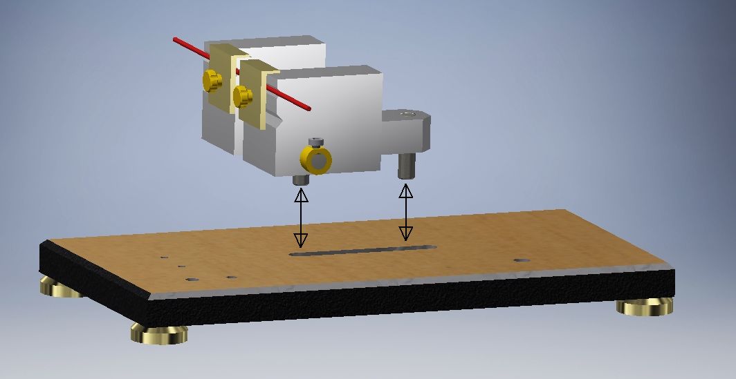
At the bottom of the intermediate rider are two sytraight guide pins that fit into a slot in the bottom plate, so that the entire rider unit can be slid forwards and backwards on this bottom plate with a stroke of 10 mm.
The heater unit.
So to melt the ends of the filaments, I wanted to press them against a thin brass plate whose temperature is at least equal to the melting temperature of the filament material, which is 210°C. I made a little brass cylinder for this, where I hard soldered the brass plate at one end. On the other side of the cylinder there is a central bore in which a heater that is often used for 3D printers is fixed. Such a heater is in fact an electrical resistance that, according to my observation, heats the cylinder to 210°C with a current of about 2 amps and thus also the thin brass plate. Across the cylinder is also a temperature sensor with which the temperature can be read by means of an electronic circuit that will be made by son-in-law Maarten and of which I have no understanding but Maarten all the more.
This heater and also the temperature sensor can be purchased for a few euros at Aliexpress, click here.
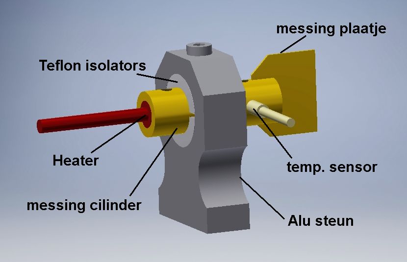
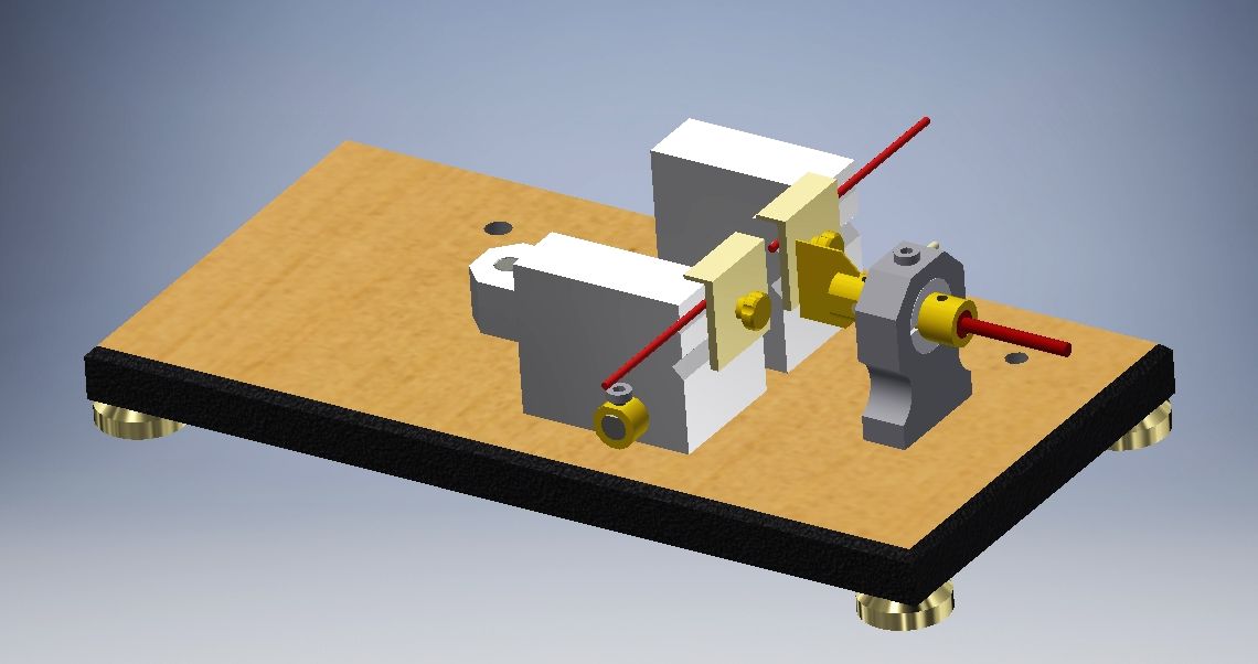
The cylinder is clamped in an aluminum support which in turn is screwed to the bottom plate. To prevent or minimize heat loss to this support, there are two Teflon dishes between the cylinder and the support that conduct heat poorly. The melting temperature of Teflon is 327°C so that it easily survives the 210°C of the cylinder.
The heater unit is positioned opposite the rider unit in such a way that the filament ends can be slid over the heated plate.
The melting process.
So experimentally I have determined that the brass plate reaches the melting temperature of the filament material at a current of about 2 amps, which is the case with a supply voltage between 12 and 13 volts on the heater. The warm-up time for this is then approximately 5 minutes. This can possibly be checked by manually pressing a test piece of a filament against the plate.
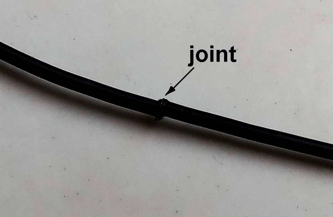
When that temperature is reached, the entire rider unit can be slid in the direction of the heater unit so that the hot plate is located between the two filament ends. Then move the two riders towards each other to press the filament surfaces against the plate with light pressure. When the filaments visibly melt, slide the rider unit back and immediately afterwards move the riders towards each other, causing the filaments to fuse together. The riders in that rear position immediately slide apart again against the stops on the ends of the slide shaft, so that the still somewhat liquid joint constricts somewhat. Lift the rider unit from the bottom plate and unscrew the pressure plates from it so that the fused filaments come loose.The joint is as strong as the filament material itself, as far as I can tell.
A more or less large bulge may remain around the joint. If necessary, this can be cut away with a sharp nail clipper if it turns out that the nozzle would cause a problem when the joint was passed through it.The result in practice.
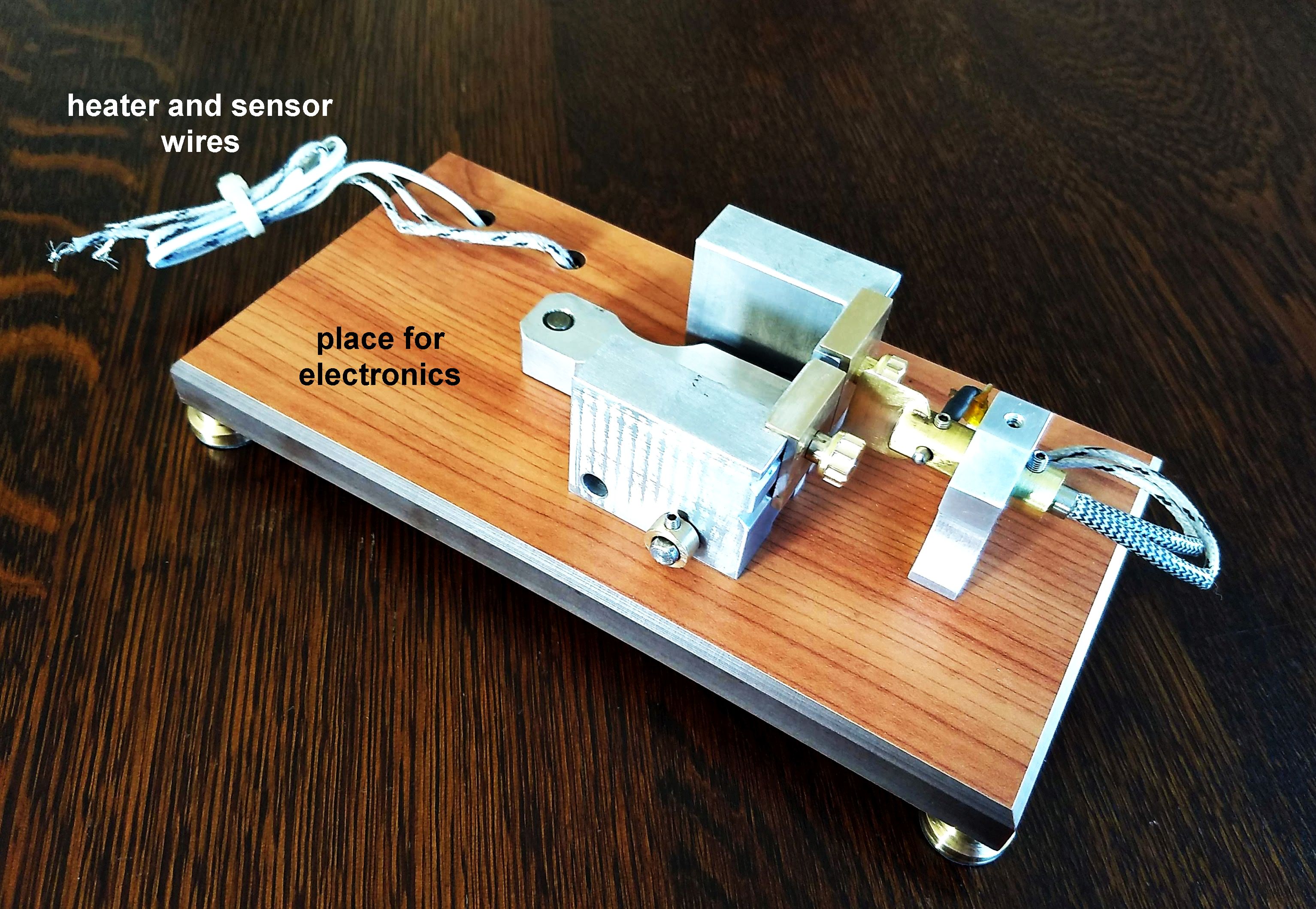
I made the bottom plate of hard Trespa plastic with a wood motif. Not only because it looks good, but also because the rider unit slides over it with lower friction than e.g. over aluminum. This bottom plate stands on four brass feet under which I have glued non-slip rubber to prevent the whole from sliding over the table during the melting process.
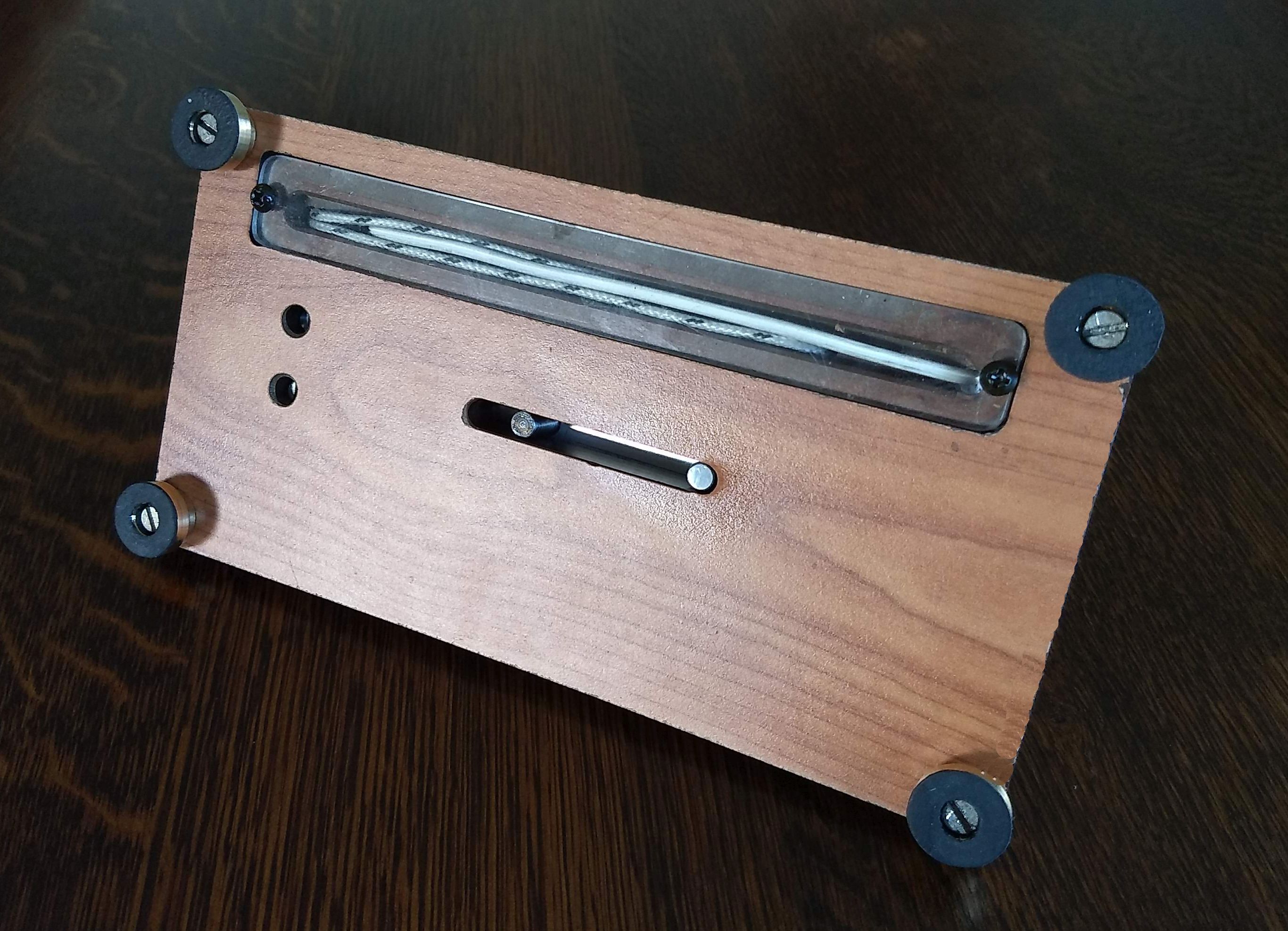
The connection wires of the heater and sensor have been led from front to back along a slot in the bottom of the bottom plate that is covered with a plexiglass plate. On that back side of the bottom plate, those wires will be connected to the electronic control circuit.
I also made the YouTube video below of this filament fuser, including some images of the melting process:
At last.
- During the tests I simply applied a fixed voltage of 13 volts to the heater and found that everything remained intact, even with a longer period of heating. However, Maarten will make an ingenious microprocessor program that, by reading the sensor, will continuously maintain the temperature of the brass plate around the melting temperature of the filaments. This is not only more attractive, but it also means that he can use a standard power supply for a laptop PC with an open voltage of 19 volts for power supply.
- I also made a CAD drawing package of this flament fuser. For a request click here.