Introduction
Already in 2001 I designed a 2-cylinder Stirling engine with a very special driving mechanism for the two displacers and the two working pistons. I have made the model "on the spot" on the basis of some simple sketch work. I did not make a CAD drawing package at that time simply because I was not able to do that at that time. Now I can, so I decided to make a complete CAD plan after all because this is a very special and excellent running model and I often get requests for a drawing plan. On this occasion I also applied some significant improvements. The latest update of this CAD plan is dated July 2016.
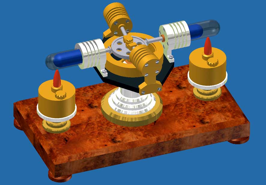
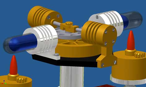
The CAD figures below and to the right on this page illustrate this design:
Figure 1
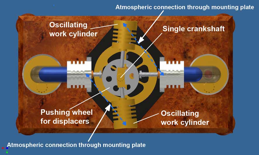
Figure 2
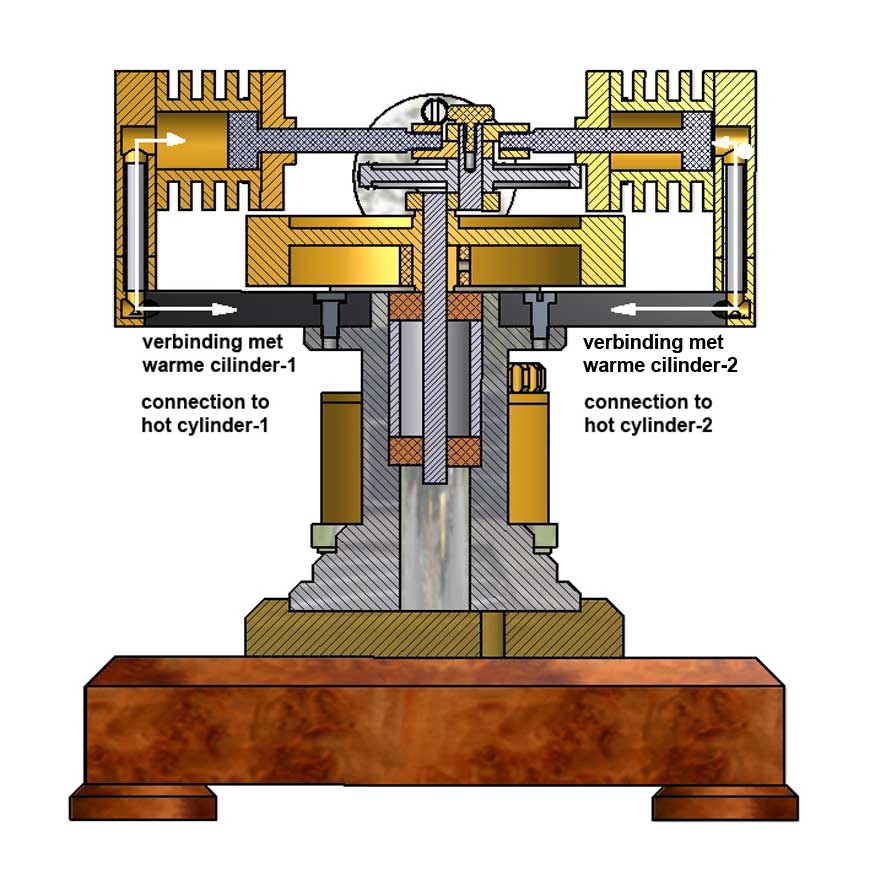
Figure 3Some details of this concept
The four cylinders and the flywheel are in the horizontal plane. The vertical crankshaft with the flywheel on it rotates on ball bearings in the central aluminum support and has only one single crank pin. The connecting rods of the two working pistons are coupled to this crank pin and there is also a wheel on it that drives the two spring loaded displacers. So this wheel is moving back and forth with the same stroke as the working pistons.
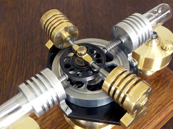
The working pistons have rigid axles so that the working cylinders are oscillating on hollow pipes when the engine is running. These hollow tubes are also used for the atmospheric connection between the hot and cold cylinders by means of two longitudinal bores through the (black) mounting plate; see figures 2 and 3.
This construction automatically ensures that the movements of the displacers, and that of the corresponding working pistons exactly are 90 degrees phase shifted which is required for the Stirling process. The phase shift between the two cylinder systems also is automatically 180 degrees with this construction so that the two systems work together helping the process over its dead moments in the process.
All together this is a special and relatively simple driving mechanism whereby the oscillation of the working cylinders adds something special to the appearance and the movement dynamics of the engine.
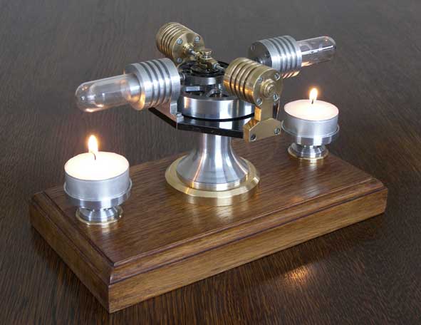
The energy of the engine can be supplied by two alcohol burners or by two waxine tea lights. They both fit in the same containers of what the height can be adjusted through a threaded spindle on it. With alcohol burners a speed of about 600 revolutions per minute can be obtained. Tea light candles are more friendly to use in many respects than spirit burners, but the power generated thereby is a little lower. Then one must be content with a more lower speed of about 300 rpm; more suitable for safe and happy running on a walnut table in the living room.Drawing plan.
I made an 8-sheet CAD drawing plan for this Stirling. It is available for everone interested; click here for a request.
Beautiful replica made by Huib Visser !
Beautiful replica from Georg Strobel: