Introduction
Armed with my experiences with the 2-cylinder 4-stroke engines Mk1 and MK2 where 2 opposed graphite pistons are running in 2 glass cylinders I now got the intention to make a 1-cylinder version of that.
To give such a "half copy" some extra appearance l decided to integrate a rotary valve in the cylinder head for the intake and the exhaust as well with what the one-way intake ball valve also can be eliminated.
In consequence this engine became an extremely simple and compact design with what the combustion fires will be visible again through the glass cylinder.
The design
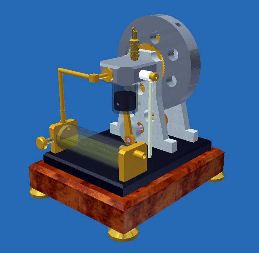
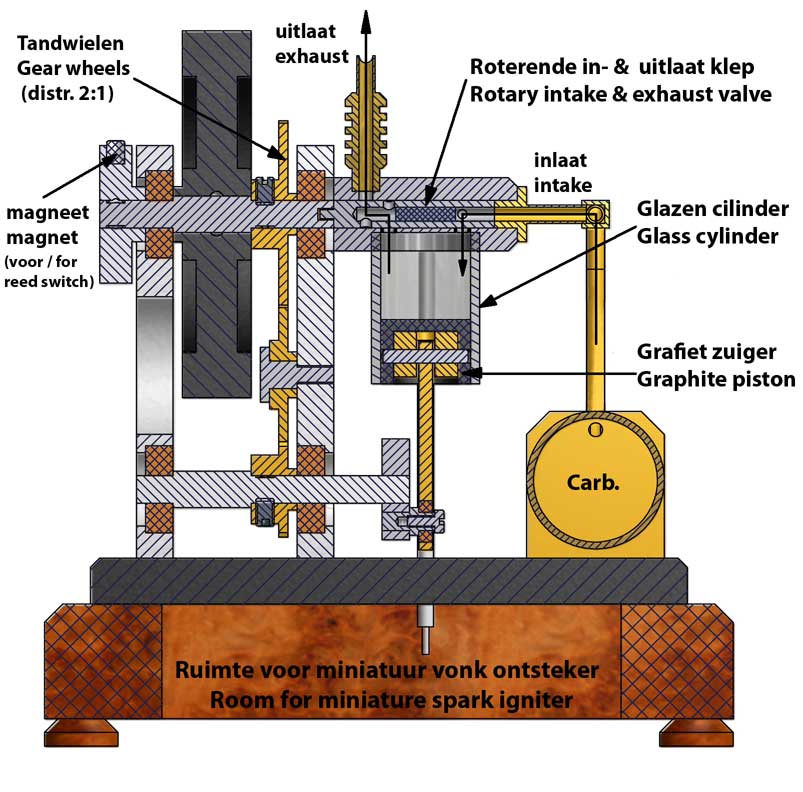
The CAD pictures below illustrate the design (MK1 version with gear distribution):
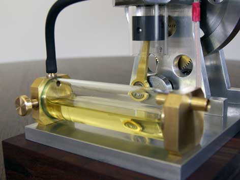
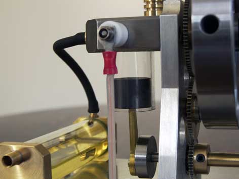
The glass cylinder and graphite piston.
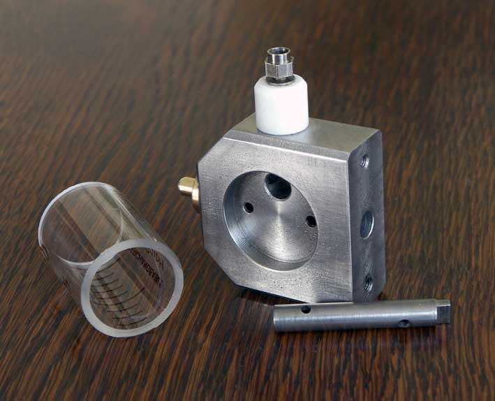
As I did before with the 2-cylinder MK1 en MK2 4-stroke engine I cut the glass cylinder out of a glass syringe with a very precise inner diameter. These 20ml "Optima-Fortuna" syringes are for sale everywhere, for instance at:
http://www.sigmaaldrich.com/technical-service-home/product-catalog.html
I glued the cylinder in the brass cylinder head with Loctite 603. The diameter of the recess chamber for that must have a 0.01mm oversized diameter so the thin liquid Loctite 603 can fill that space nicely. After hardening at about 50 degrees Celsius during half an hour the joining is extremely well and survives all the engine attacks.
Through the glass cylinder the combustion fires are beautifully visible in a somewhat subdued room lighting and this also adds something very special to this model. Another advantage is that it is also nice to see whether the gas mixture ignites well and at every cycle. In addition, you can determine with the color of the ignition if the ratio of the gas mixture is optimal. A yellow color means that the mixture is too rich with what the engine is not running very well or even not at all. Adding some more air to the gas mixture with the controller on the carburetor the combustion color changes from yellow to blue to indicate that the optimal gas composition is reached: one part of petrol vapor and about 14 parts air.
The graphite piston is made with a clearance of about 0.01mm (or even less) in the cylinder and is sliding in that almost without friction and also almost leak-free. A brass fork is glued in the graphite piston (also with Loctite 603) to avoid the piston pin charging the rather weak graphite.
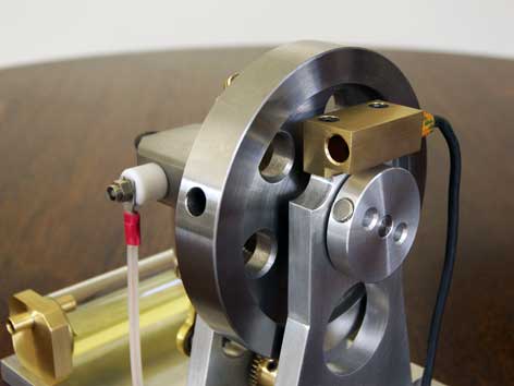
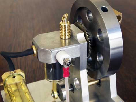
The rotary intake and exhaust valve.
I made a similar rotary valve for the intake as well as for the exhaust for my "Ridders 4-stroke engine ". There this valve was outside the cylinder head, but here I integrated it in the cylinder head, making the construction more compact and with less dead space in the cylinder. With the 2-cylinder versions with the 2 opposed pistons this was not possible because these engines don't have a cylinder head at all. The valve will become somewhat hotter here, reason why I made both the cylinder head and the mandrel of the valve from grey cast pearlitic iron to avoid any risk of jamming. The thermal expansion of this material is very low and at least equal for both elements. Furthermore this cast iron is more or less self-greasing due to the high carbon content, it is wear-resistant and doesn't tend to dig into. These properties are reason for me to use it for the cylinders and pistons of all my combustion engines, except of course when I make glass cylinders and graphite pistons as I did here.
I deliberately didn't make the valve mandrel and the fly wheel axle out of one part to avoid a radial charge of the mandrel in the bore of the cylinder head. The mandrel is driven by a simple carrier on the fly wheel axle that fits with some clearance in a slot in the mandrel. I applied this construction also with my "Ridders 4-stroke" and with success; see picture below:
The coupling between the crank shaft and the rotary valve.
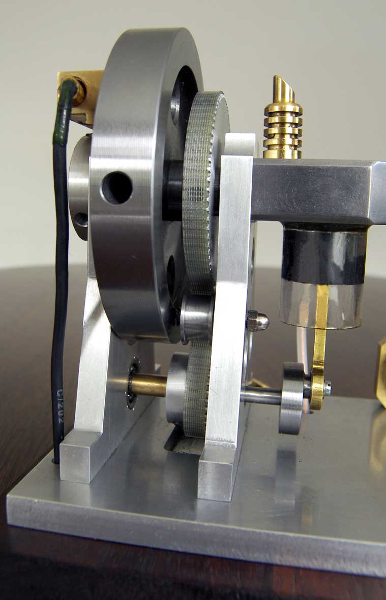
Here again I had to make a choice between gear wheels or a timing belt with a distribution ratio of 2 to 1 which is always necessary with 4-stroke engines. Because the center distance between the crank shaft and the rotary valve is mainly determined by the dimensions of the cylinder/piston combination and the stroke of the piston it is purely a matter of coincidence to find gear wheels that exactly fit in the design unless you make these wheels yourself. I did that once with rather satisfying result, but they were not perfect. So I had some doubts to do that again because it is just outside my scope to make perfect gear wheels for the time being and I think that counts for more model builders.
It suddenly became another story when I found by accident some nice gears wheels in my scratch box with respectively 80 and 40 teeth although they both were too small to bridge the distance between the crank shaft and the valve axle. But I was lucky again finding a third gear wheel of the same family and putting that in between the other two it fitted perfectly! So that's the reason you see on the CAD pictures above three instead of two gear wheels.
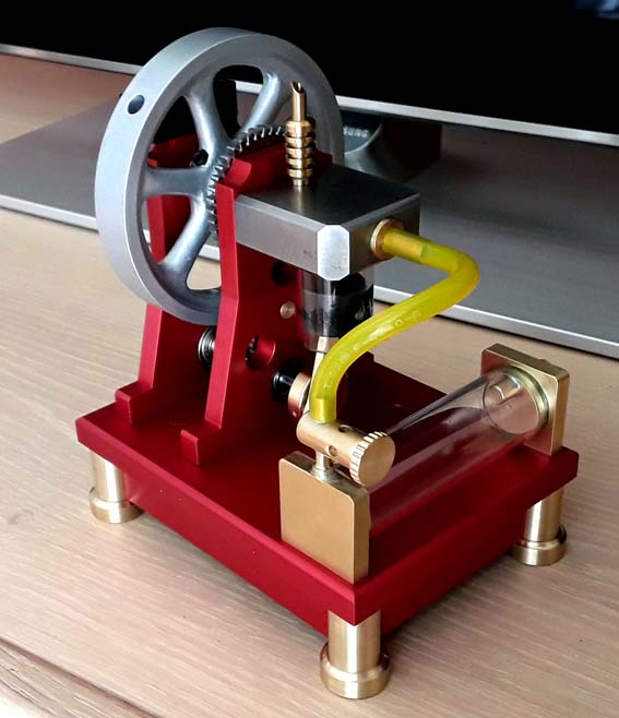
The advantage of gear wheels is that they don't cause radial load on the axles which is more or less the case with geared timing belts, although that is not a such very serious effect. Next time and in other circumstances I will have a plea for geared timing belts again I suppose.MK2 version with geared timing belt instead of gears.
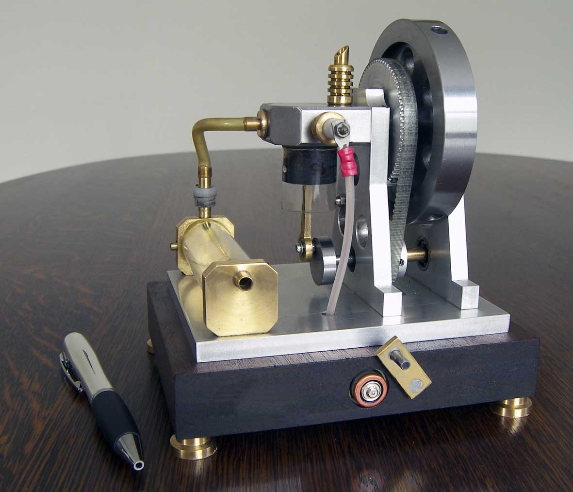
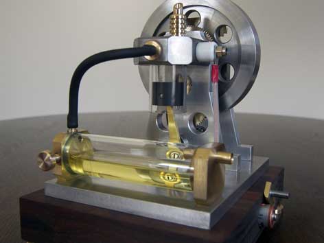
Because at one point one of the gears broke down I replaced the gears later with a geared timing belt. In hindsight it is still a better system which is more flexible and noiseless. The engine now looks as shown in the pictures below:
The spark ignition.
The typical characteristics of this concept.
Also here I used the mini spark igniter system with the "Blokker circuit" that I build in the wooden base completely this time.
I could not make the spark plug on top of the cylinder head as usual because here the rotary valve is in the way. So I made the spark pug on the side face of the cylinder head with a perpendicular bore in the cylinder head to allow the spark making atmospheric contact with the compressed gas mix in the cylinder. I did not do this before, but it appeared not to be any problem.
Maybe this little engine looks somewhat dull but that often is a consequence of making things extremely simple. I admit that 4-stroke model engines with all classic elements on it are much more eye-catching, but I can't make that works of art or maybe I don't want to do that. It is a matter of skills, possibilities, style and choice. But the appearances of simplicity can be deceptive sometimes and, if you allow me, that could be the case here for the real fancier or for a attentive spectator. How often will you see a 4-stroke engine that:
1.Has a glass cylinder through what you can see the combustion fires and in what a graphite piston is running with neglect able friction and leakages without a piston ring and any lubrication;
2. Don't have poppet valves with their rather complex driving mechanisms of springs, tumblers, valve pushers and cam discs;
3. Has a process adjustment that is implicit anchored in the hole pattern in the rotary valve mandrel and that never can cannot drift or fluctuate any more;
4. Has no systems for forced cooling or lubrication;
5. Has a miniature spark igniter that easily can be self made from a circuit in a very cheap gas lighter;
6. Has a carburetor consisting of a tank with simple arrangements for the air regulation and with what no problems occur with respect to choking, flooding the engine, rooting or wetting the spark plug;
7. Have a childish simple external crank shaft without any accurate grinding work and with no need for a crank case;
8. Can be made with standard lathing and milling work from also standard materials.As with all my little engines there are limitations of course: don't try to pull a cow out of a ditch and/or let them run constantly for a very long time. It are friendly little things that must be treated friendly, meant to run for 5 to 10 minutes max. which is more than enough for a successful demonstration according to my experience.
Video:
Drawing plans.
The plans for this Mk1 or Mk2 engines are available for everyone interested; for a requesty click here.
Alternative for the glass cylinder
If one cannot obtain this very special glass (not unlikely) and/or graphite one can make the cylinder from bronze and the piston from cast iron. Well made (fairly leak free and with low friction) the engine will run also. The only difference will be that the combustion fires will not be visible; pity of course, but the rest of the engine and the performance is the same.
Beautiful version by Huib Visser
Horizontal with timing belt 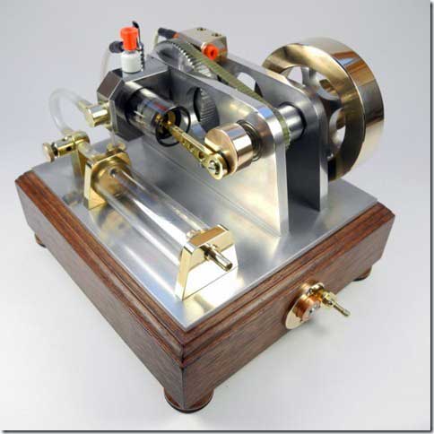
Nice replica by Irek Szczygiel
Brilliant replica made by
Stefan Kohler and Lukas Fischer:
Nice replica made by
Antonio Fattore
Very nice replica's made by
Bart, Jeroen and Ben
van Duin:
Beautiful replica
made by
Amith Perera: