Introduction
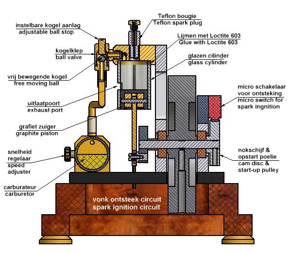
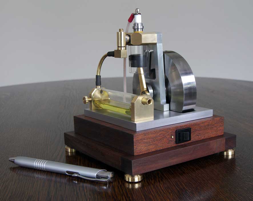
Recently I made the 4-stroke engine with glass cylinder with what you can see the combustion fires through the glass cylinder. Encouraged by the success I conceived the plan to make a 2-stroke version of that. This because a 2-stroke is much simpler than a 4-stroke due to the absence of moving valves and distribution systems with gears or timing belts, but also because this was a special challenge in this case as will be seen further on.
With a 2-stroke engine the fresh gas mix is sucked-in below the piston when it is moving upwards compressing the previous sucked-in gas mix above the piston. This gas mix ignites at its maximum compression when the piston is arrived at its most upper position. When the piston is moving downwards again during the power stroke the new fresh gas mix is compressed below the piston in the crank case. When the piston has arrived in its lowest position it just has opened the exhaust port in the cylinder wall through what the burned gasses will escape. At that same moment the compressed gas mix below the piston is injected above the piston and flushes the remaining burned gasses out of the cylinder through the exhaust port. The fresh gas mix above the cylinder is compressed when the piston is moving upwards again after it has closed the exhaust port and the 2-stroke cycle is repeating.
But here I didn't want to close the bottom of the glass cylinder with a crank case or a flat plate through what a rigid piston rod most move up and down leak free. A crank case is far to complex for me to make and a rigid piston rod must be extended bij a second driving rod to make a swiveling connection to the crank shaft possible. This should make the construction relative large and apart from that these constructions detracts the free sight on the transparent glass cylinder. So I wanted to fix the glass cylinder only to the cylinder head with Loctite 603 which I did successfully before with my former 4-stroke glass cylinder versions.
So, to make a 2-stroke engine with a glass cylinder like this I had to solve two problems:
1. Making an exhaust hole in the wall of the glass cylinder;
2. Compressing the fresh gas mix in another way than below the piston.
The concept
1. The glass cylinder with exhaust port
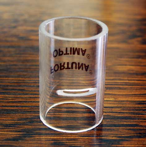
I cut the cylinder out of a glass syringe ( brand Fortuna Optima 20ml) as I also did for my 1- glass cylinder 4-stroke engine. The wall thickness is 2mm and the tolerance of the inner diameter is extremely small: +/- 0.01mm which is necessary to let a piston fit air-tight in it.
Making an exhaust hole in the glass looked as a problem, challenging at least. But with the aid of my glass cutting device I easily could grind a slot in it. The picture below shows the result:
Initially I was afraid that the slot would decrease the glass strength seriously, but the luck was with the stupid. With no force I could break the cylinder and it even survived a spirits flame heating the slot continuously! During the combustion of the gas mix the piston is above the exhaust slot so the slot doesn't know what happens there. The glass cylinder survives the combustion process easily as it also did with my previous other glass cylinder engines.
I glued the cylinder in the brass cylinder head with Loctite 603. The diameter of the recess chamber for that must have a 0.01mm oversized diameter so the thin liquid Loctite can fill that space nicely. After hardening at about 50 degrees Celsius during half an hour the joining is extremely well and survives all the engine attacks.
Through the glass cylinder the combustion fires are beautifully visible in a somewhat subdued room lighting and this also adds something very special to this model. Another advantage is that it is also nice to see is whether the gas mixture ignites well and every cycle. In addition, you can determine with the colour of the ignition if the ratio of the gas mixture is optimal. A yellow colour means that the mixture is too rich with what the engine is not running well or not at all. Adding some more air to the gas mixture with the controller on the carburettor the combustion colour changes from yellow to blue to indicate that the optimal gas composition is reached: one part of petrol vapour and about 14 parts air.
I simply glued this glass cylinder in the cast-iron cylinder head with Loctite 603 which creates a stunning strong and air-tight connection and it permanently withstands the temperature of the cylinder which, moreover, is not much higher than 80 to 90 degrees Celsius.
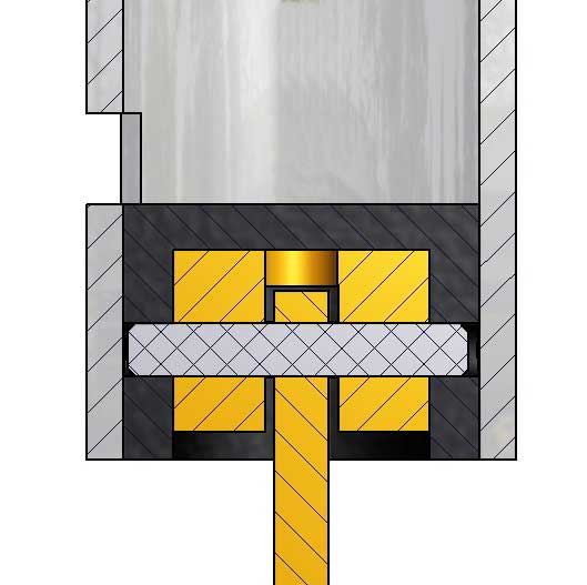
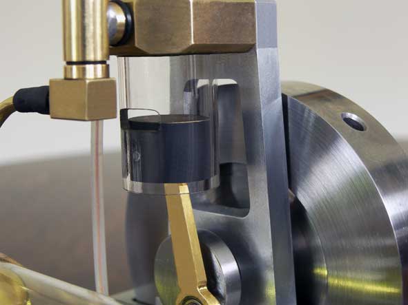
2. The graphite piston.
In this case graphite is the most ideal material for the piston. The friction of the self greasing graphite in the glass cylinder is practically zero with a clearance of 0.01mm or even less without any need for oil lubrication. The thermal expansion is very low and somewhat smaller than for glass so no jamming can ever occur. Graphite is non-corrosive and survives the hot combustion gasses easily.
I glued a brass piece in the piston (also with Loctite 603) to strengthen the connection between the driving rod and the piston. The bore for the piston pin was made through the combination in one treatment after gluing the brass piece; see picture below.
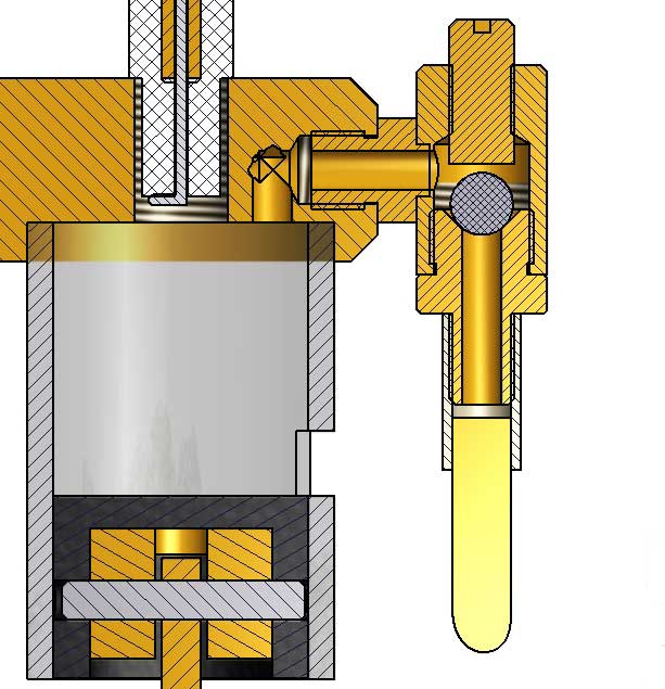
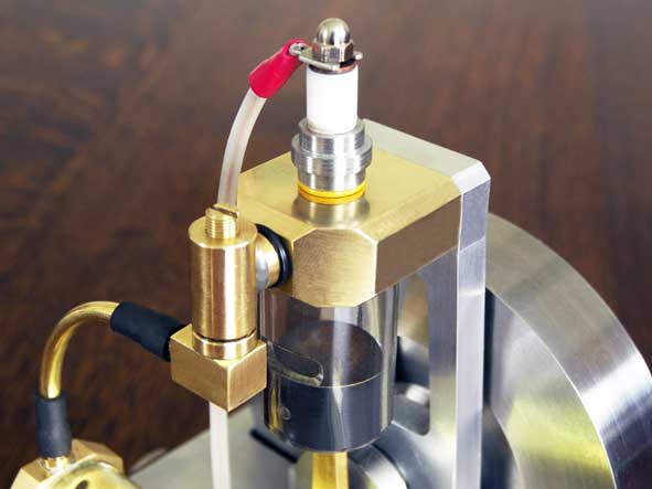
3. The ball valve.
The ball valve between the cylinder head and the carburettor is a crucial part and plays a special role in the process as I will explain further on. Very important is that the not spring-loaded ball has a small free stroke in the vertical direction. The optimum adjustment is rather critical here and must be done with a running engine by screwing the stop above the ball in or out.
Except for the steel ball everything is made from brass. The ball seat has a 90 degree top angle and must made very smooth with a sharp cutter in the lath.
Process description
1. The gas exchange process
Initially I assumed that above the piston of a 2-stroke engine a partial vacuum (under pressure) never can occur so no fresh gas mix can be sucked-in there. That is after all the reason why the fresh gas mix with a normal 2-stroke engine is sucked-in below the piston and compressed again in the crank case to flush the cylinder above the piston at the moment it has arrived in its lowest position when it open the exhaust port.
For the reasons I mentioned in the introduction I wanted bottom side of the glass cylinder to be open so I assumed that I needed some kind of double-acting pump to suck the gas mix out of the carburettor and compress that to be injected in the cylinder via the ball valve in the cylinder head when the piston is in its lowest position. I spend a lot of time to design and make such a double-action pump that was driven by the engine itself with a magnet system. I will not enumerate all my experiences with that here because I did this earlier on the "log book" that I removed because it has become outdated facts now. Basically it appeared to be possible to make such a pump but it appeared rather complex to keep it small and also difficult to let it make just enough pressure and flow that is needed for a good flushing process.
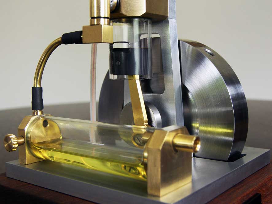
But during these experiments I did an unexpected and very surprising discovery: even without the pump there was a large gas flow in the carburettor making waves on the petrol surface that I could see through the glass wall of the carburettor. I first thought that is was caused by the so called "Kadenacy effect". A thermodynamic process with what a partial vacuum can occur in the cylinder when the hot combustion gasses escape through the exhaust opening and that sometimes is used to improve the efficiency of 2-stroke engines by making special exhaust mufflers. But this gas flow through the carburettor also happened when I disconnected the spark ignition and then no combustion can occur and, for that, also no Kadenacy effect of course.
So my explanation for that gas flow is another one and it has mainly to do with the fact that my 2-stroke engine isn't a normal one. The biggest difference is that I use a ball valve in the cylinder head instead of a fixed intake hole in the cylinder wall as is usual for all other 2-stroke engines.
My explanation for this remarkable phenomenon is as follows:
At the moment of ignition a high combustion pressure occurs that will keep the ball in the valve on its seat during the whole power stroke. If the piston after exhausting is moving upwards again non-flammable gas is compressed. I assume that this will be mainly very hot air caused by the Kadenacy effect, presumably mixed with some contamination of burned gasses. Due to the high temperature the gas density will be relatively low so the compression pressure will be lower than with compressing cold gas mix out of the carburettor. When the piston arrives in its upper position and is changing direction the ball in the valve most probably will bounce somewhat causing the compression pressure to be eliminated instantly to normal pressure. There will be a spark then but also a "miss" because the non-flammable gas cannot ignite and the atmospheric pressure will remain. When the piston goes down there will be a partial vacuum causing the ball in the valve to lift from its seat and gas mix from the carburettor will be sucked-in. This gas mix will be mixed with the air that shortly before was pushed back in the carburettor. Not so bad as such because the primary gas mix in the carburettor is always too rich and need to be added with air after all. Apparently the petrolvapour/air ratio is still greater than the optimal 1 to 14 because I still have to add extra air with the regulator on the carburettor to let the engine run well. As said, there must be some burned gasses also in that gas mix, but that seems little because the gas mix is igniting nevertheless.
The ball valve has an adjustable stop with what the vertical stroke of the ball can be limited. This adjustment appears to be rather critical here but it is the key for the success at the same time; the luck of the stupid I suppose. With the optimal adjustment of the ball valve and the carburettor I achieved easily engine speeds of about 1000 rpm and sometimes even 1500 rpm. Remarkable is the fact that the engine can run with a very low 150 rpm speed also, probably because the engine is running mechanically as "driven by the wind" due to the very low friction of the graphite piston in the glass cylinder, the absence of counteracting pressures below the piston and ball bearings on the rotating parts.
I cannot draw another conclusion than that this 2-stroke engine is acting as a 4-stroke engine. Or, with equal justification, one can say that this is a 4-stroke engine with a very simple 2-stroke construction; it just depends how one looks at it.
I visualized the very remarkable process with an animation in the video below that I made after I got this engine to run well:Video:
One can clearly hear the cyclically misses especially at very low speeds and with good attention one can see some of these misses on the slow motion part of the video; fascinating at least for model building enthusiast.
The power of this engine will be rather low I suppose but that doesn't bother me at all; I don't intend to pull a cow out of a ditch with it !
2. The spark ignition mini "Blokker" circuit for this that is working well for all engines on which I installed that. But I on
Initially I applied the also knew that the spark of that is less powerful than that of a classical motor bike ignition coil. I experienced earlier that 2-stroke engines in general need a more powerful spark than 4-stroke engines. The reason must be that the purity of the gas in the cylinder is less good in 2-strokes due to the somewhat poor flushing process that not always remove all of the burned gasses for 100%. In fact I doesn't have a flushing process here, but as said before there will be some remaining burned gasses as per definition with this process. When I connected provisionally a circuit with the motor bike coil the engine runned perfect and reliable. I sometimes use a little glow lamp as a spark indicator and with that I could see clearly that the sparks were much more powerful without having any tendency to extinguish. When I connected the mini system again in the same circumstances the engine did run, but sometimes hesitantly or not at all. I must conclude that the mini igniter is a borderline case for this engine, at least as long I cannot improve the gas purity in the cylinder for what I do not have much hope for the time being. It looks as if this is a principle side effect of this remarkable process.
So I decided to install a classical motorbike coil instead of the mini system; a little bit pity, but one cannot force physics to fulfil all your wishes. Not insurmountable, because I just could build (hide) this bigger coil in the wooden base of the engine.
2. The fly wheel
Initially I made a nice fly wheel from scrap brass material but it appears to be too light. Not that strange because the fly wheel must help this engine through 3 powerless strokes every 4-stroke cycle. So I made a new steel fly wheel with some greater diameter and mainly a lot heavier: about 1 kg instead of the 0.5kg brass wheel. The effect was unmistakable and it is nice to see how this fly wheel helps the engine to survive the powerless strokes, especially at very low speeds.
Finally
This engine is indisputable the most crazy thing I made so far. In principle the process is somewhat out of control in the sense that it is lives its own life more or less, mainly caused by the accidental behaviour of the little ball valve. But nevertheless the engine is running fine and reliable with it, helped by the very low system frictions, a rather heavy fly wheel and the rather strong sparks.
The not 100% pure gas mix is igniting indeed, but with alternating explosive forces judging at the video pictures, although this can be caused by stroboscopic film effects as well; who can tell?
The efficiency will not be that good, at least not compared to nice controlled 4-stroke engines. But for sure it is spectacular to see the combustion fires in the cylinder on the video and the flame coughs squirting out the exhaust port.
This engine excels in extreme simplicity if I may say so, having only a cylinder with piston, a little ball valve, a fly wheel, a spark maker and a simple carburettor; in fact not more than that. So no driven poppet valves with cam discs, pushers and tumblers, no distribution system with gears or timing belts, no cooling or lubricating systems, simple external crank shaft without crank case, etc. Maybe therefore a little bit dull to see, except when one realizes what kind of special process is happening here and looking at the combustion explosions when the room is darkened somewhat.
It doesn't have any practical use of course, but that is almost always the case with model engines. I know people who make complete cathedrals by gluing thousands of match sticks together; a fantastic performance I think, but one cannot do a church service in that either.
Under the motto "the crazier the better" and "a child hand is easily filled" I am again very satisfied and charmed with the result.
Alternative for the glass cylinder
If one cannot obtain this very special glass (not unlikely) and/or graphite one can make the cylinder from bronze and the piston from cast iron. Well made (fairly leak free and with low friction) the engine will run also. The only difference will be that the combustion fires will not be visible; pity of course, but the rest of the engine is the same.Drawing plan.
I made a CAD drawing plan for this engine that is available for any-one interested, for a request click here.